Local transmit coil with integrated safety device

a technology of local transmit coil and safety device, which is applied in the direction of measurement device, magnetic measurement, instruments, etc., can solve the problem that the day sar-monitoring device is not equipped to monitor the highly restricted threshold value of fpo mod

Active Publication Date: 2017-03-16
SIEMENS HEALTHCARE GMBH
View PDF4 Cites 5 Cited by
  • Summary
  • Abstract
  • Description
  • Claims
  • Application Information

AI Technical Summary

Benefits of technology

[0020]In an embodiment, the local transmit coil includes a magnetic field sensor for detecting the magnetic excitation field. The magnetic field sensor may include, for example, one or a plurality of receiving coils, a Hall effect sensor or other elements sensitive to high frequency alternating magnetic fields. The evaluation device is in signal connection with the magnetic field sensor. The evaluation device includes, for example, one or a plurality of signal inputs for the magnetic field sensor and/or other sensor inputs for monitoring whether for example, a housing of the local tr

Problems solved by technology

However, present day SAR-monitoring devices are not equipped to monitor the highly restricted threshold values for the FPO mod

Method used


Image

  • Local transmit coil with integrated safety device
  • Local transmit coil with integrated safety device
  • Local transmit coil with integrated safety device

Examples


Embodiment Construction

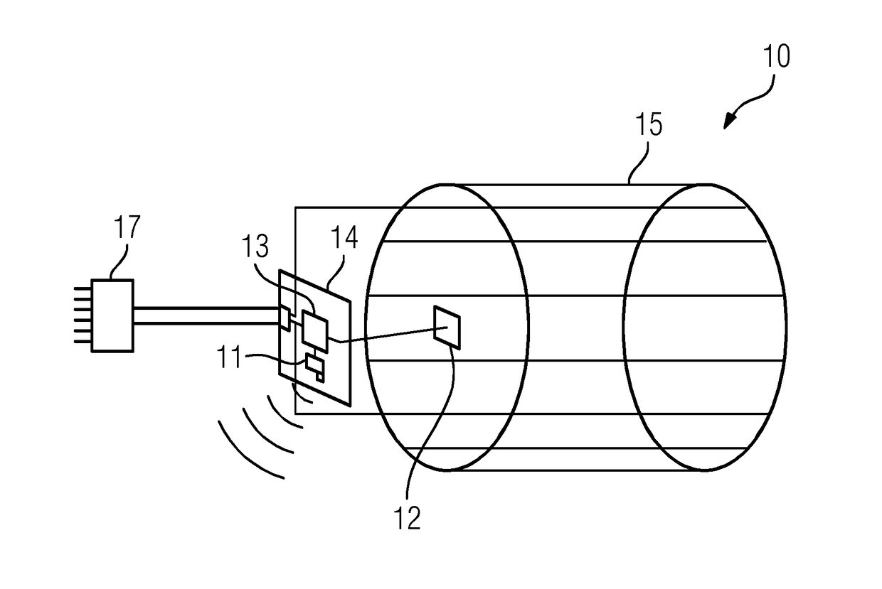
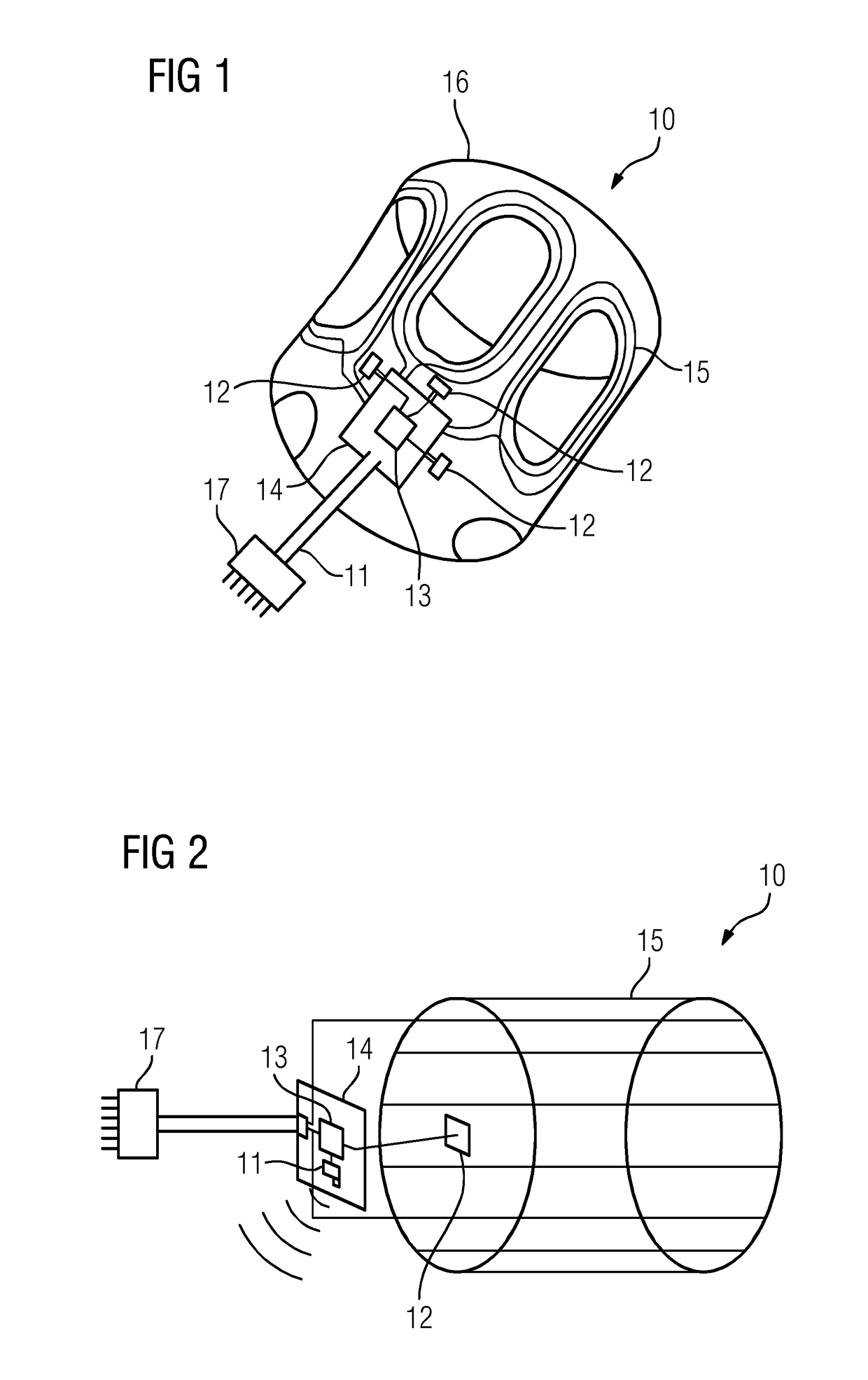
[0037]FIG. 1 depicts a diagrammatic view of a local coil 10 according to an embodiment. The local coil is depicted as a head coil. In FIG. 1, for greater clarity, the local transmit coil 10 is shown without an outer shell of a housing 16, such that the internal components are visible.

[0038]The local transmit coil 10 includes a housing 16, in which coil windings are arranged as transmitting antennas 15 for generating an alternating magnetic field. Depending on the type of local coil, there may be one or a plurality of coil windings.

[0039]The transmitting antennas 15 are electrically connected to a power supply module 14. The power supply module 14 provides distribution of one or a plurality of transmission signals that are supplied to the local coil via electric cables. These electric cables may be part of the signal transmission device 11. At the end of the cable, a plug 17 is provided to create an electrical connection with a magnetic resonance tomograph 20.

[0040]The local transmit...


PUM


Abstract

A local transmit coil for a magnetic resonance tomograph is provided. The local transmit coil includes a signal transmission device for signal transmission to the magnetic resonance tomograph, and a transmission antenna for generating a magnetic excitation field. The local transmit coil further includes an evaluation device for monitoring a function of the local transmit coil. The evaluation device is configured to transmit a status signal relating to the local transmit coil via the signal transmission device.

Description

CROSS-REFERENCE TO RELATED APPLICATIONS[0001]This application claims the benefit of DE 10 2015 217 723.8, filed on Sep. 16, 2015, which is hereby incorporated by reference in its entirety.TECHNICAL FIELD[0002]Embodiments relate to a local transmit coil for a magnetic resonance tomograph.BACKGROUND[0003]Magnetic resonance tomographs are imaging devices that, in order to represent an examination object, align nuclear spins of the examination object with a strong external magnetic field. The tomograph excites an alternating magnetic field for precession around the alignment. The precession or return of the spins from the excited state to a state with lower energy generates an alternating magnetic field. The alternating magnetic field is received via antennas.[0004]With the aid of magnetic gradient fields, a spatial encoding is imprinted on the signals. The spatial encoding subsequently allows the received signal to be assigned to a volume element. The received signal is then evaluated ...

Claims


Application Information

Patent Timeline
IPC IPC(8): G01R33/341G01R31/06G01R31/72
CPCG01R31/06G01R33/341G01R33/288G01R33/34046G01R33/34076G01R33/36G01R33/3692G01R31/72
Inventor DEMHARTER, NIKOLAUSVESTER, MARKUSWEI ENBERGER, VOLKER
Owner SIEMENS HEALTHCARE GMBH
Why Eureka
Try Eureka