Percussive drill bit with multiple sets of front cutting inserts

a drill bit and insert technology, applied in drill bits, drilling accessories, earth-moving drilling and mining, etc., can solve the problems of limiting the penetration rate of the bit and high wear rate, and achieve the effect of maximising the penetration rate and maximising the service life of the bi

Inactive Publication Date: 2017-03-23
SANDVIK INTELLECTUAL PROPERTY AB
View PDF3 Cites 0 Cited by
  • Summary
  • Abstract
  • Description
  • Claims
  • Application Information

AI Technical Summary

Benefits of technology

[0005]It is a primary objective of the present invention to provide a percussive drill bit that is configured to m...

Problems solved by technology

Accordingly, the inserts at those regions of the bit with the fewer neighbour...

Method used


Image

  • Percussive drill bit with multiple sets of front cutting inserts
  • Percussive drill bit with multiple sets of front cutting inserts
  • Percussive drill bit with multiple sets of front cutting inserts

Examples


Embodiment Construction

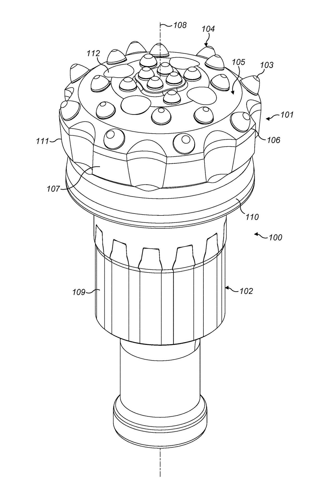
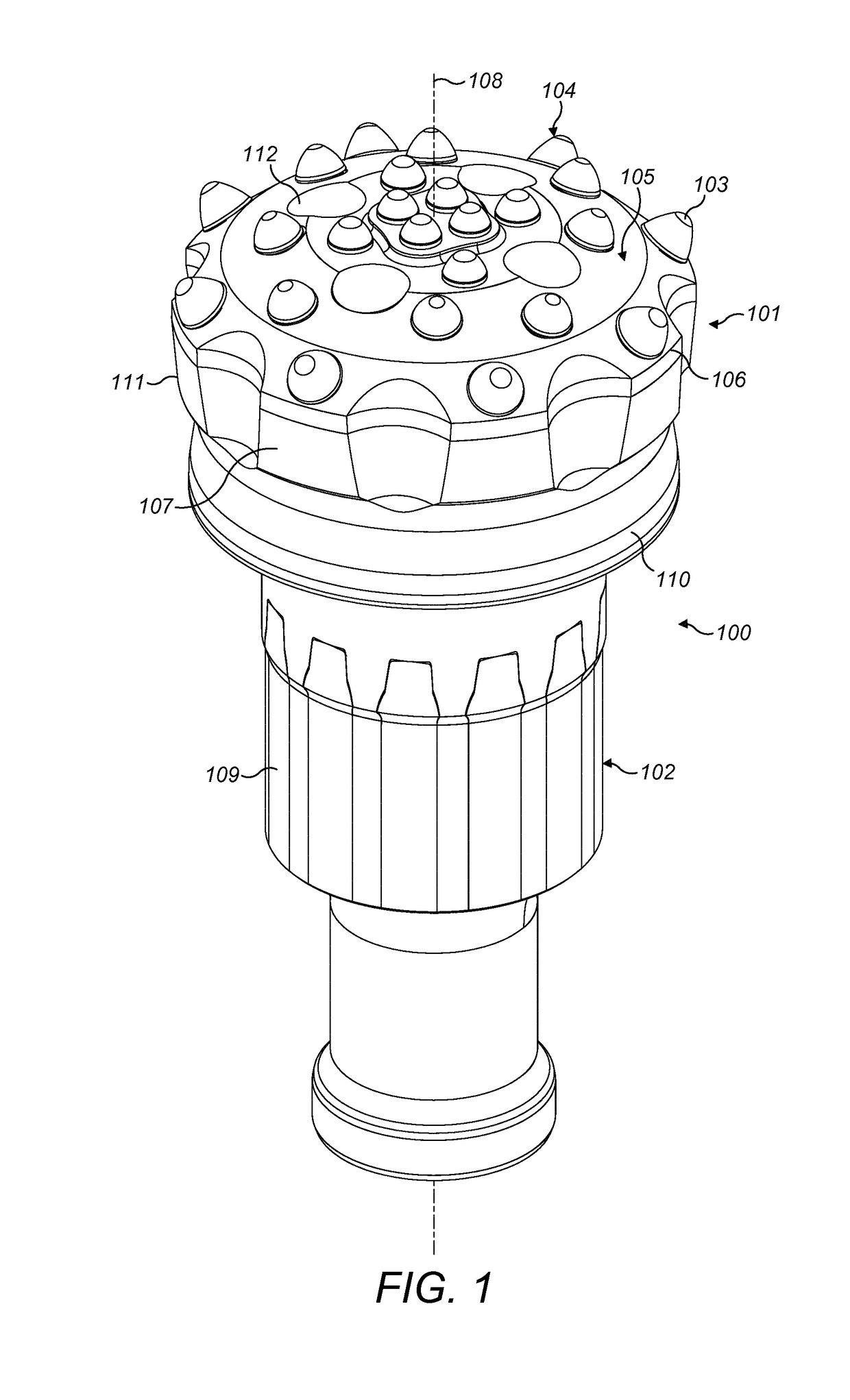
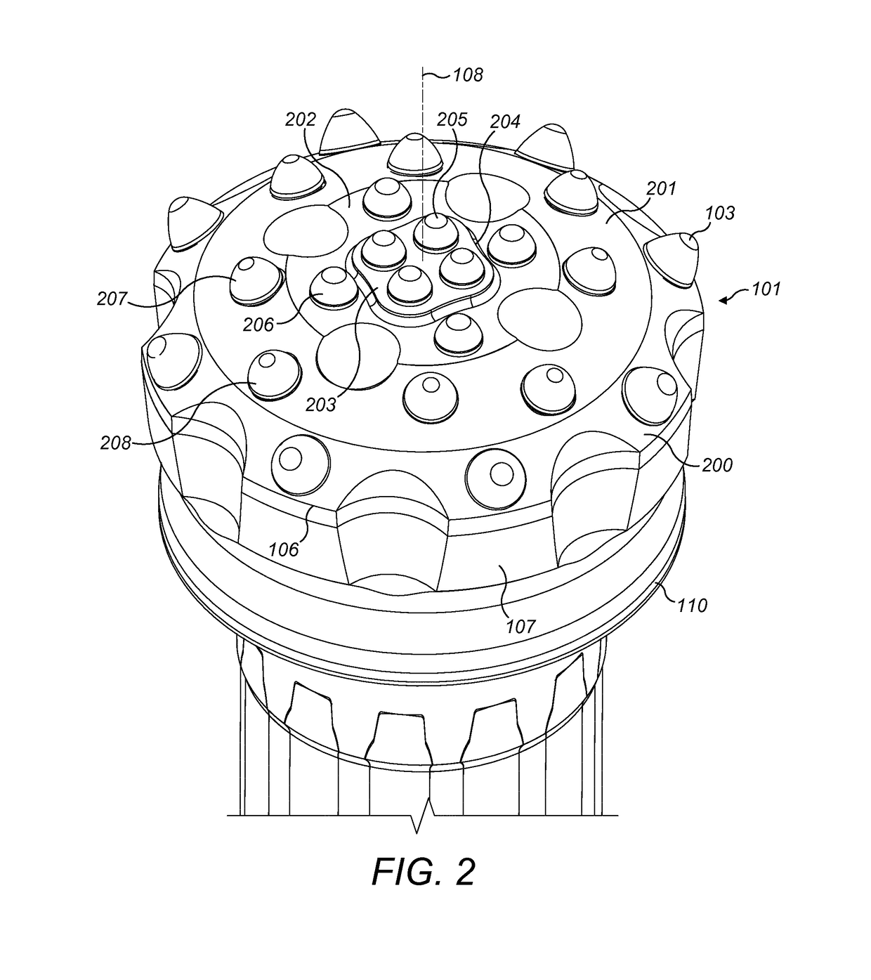
[0027]Referring to FIGS. 1 to 4 a drill bit 100 comprises a drill head 101 formed at one end of a generally elongate shaft 102 with both head 101 and shaft 102 centred on a longitudinal axis 108. Shaft 102 comprises splines 109 to engage with corresponding splines of a drive tool (not shown) that surrounds the shaft 102 during use. Head 101 comprises an axially forward section 111 and an axially rearward skirt section 110 that interfaces with shaft 102. Section 111 comprises a larger diameter than skirt 110 and is defined, in part, by an annual outermost perimeter edge 106. A forward facing front face indicated generally by reference 105 projects axially forward from edge 106 such that the forward facing part of section 111 is generally convex and comprises a dome-shaped profile when viewed from the side or in cross section. Forward head section 111 tapers rearwardly from edge 106 via a short longitudinally extending trailing surface 107 that mates with an axially forward region of ...


PUM


Abstract

A percussive rock drill bit includes a head provided with an elongate shank. A plurality of front cutting inserts are distributed at a front face of the head and are grouped into a plurality of sets, with each set being positioned at a different radial distance from a central axis. Each set of inserts includes the same number of inserts to maximize drilling rate and service lifetime of the drill bit.

Description

FIELD OF INVENTION[0001]The present invention relates to a percussive rock drill bit and in particular, although not exclusively, to a drill bit formed with a cutting head mounting a plurality of front cutting inserts arranged into sets with each set distributed at different radial positions at a front face of the cutting head.BACKGROUND ART[0002]Percussion drill bits are widely used both for drilling relatively shallow bores in hard rock and for creating deep boreholes. For the latter application, drill strings are typically used in which a plurality of rods are interconnected to advance the drill bit and increase the depth of the hole. In ‘top hammer drilling’ a terrestrial machine is operative to transfer a combined impact and rotary drive motion to an upper end of the drill string whilst a drill bit positioned at the lower end is operative to crush the rock and form the boreholes. In ‘down the hole’ drilling the impact is delivered not through the upper end of the string, but by...

Claims


Application Information

Patent Timeline
IPC IPC(8): E21B10/40
CPCE21B10/46E21B10/40E21B10/36
Inventor HEMPH, RASMUSNORDSTRAND, ANNANORDBERG, ANDERS
Owner SANDVIK INTELLECTUAL PROPERTY AB
Why Eureka
Try Eureka