Rotary cutting insert and tool having axial locking member

a technology of axial locking member and drill tool, which is applied in the direction of tool workpiece connection, twisting drill, manufacturing tools, etc., can solve the problems of disadvantageous existing drill tool assembly and insufficient centre of the inser

Pending Publication Date: 2021-05-27
SANDVIK INTELLECTUAL PROPERTY AB
View PDF21 Cites 1 Cited by
  • Summary
  • Abstract
  • Description
  • Claims
  • Application Information

AI Technical Summary

Benefits of technology

[0006]It is an objective of the present invention to provide an axial lock of the insert at the support body that is not detrimental to a centring of the insert in position at the support body. In particular, it is an object to provide an axial lock of th...

Problems solved by technology

Existing drill tool assemblies of the aforementioned type are disadvantage...

Method used


Image

  • Rotary cutting insert and tool having axial locking member
  • Rotary cutting insert and tool having axial locking member
  • Rotary cutting insert and tool having axial locking member

Examples


Embodiment Construction

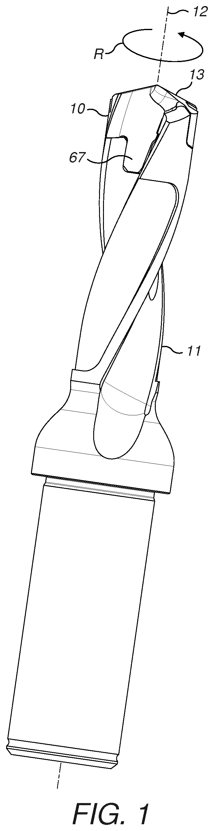
[0039]Referring to FIG. 1 a cutting tool implemented as a drilling tool comprises an elongate support body 11. A cutting insert 10 is releasably mounted at an axially forward end of support body 11. Insert 10 comprises an axially forwardmost, axially forward facing cutting region 13 and an axially rearwardmost mount region 67. Mount region 67 and the axial forward end of support body 11 are shaped complementary to one another both axially and radially as described in detail below so as to provide control and management of the transmission of loading forces between insert 10 and support body 11 during use. Such loading forces include axial and radial forces in addition to torque resultant from the rotation of the cutting tool in direction R about a central longitudinal axis 12 extending though insert 10 and support body 11.

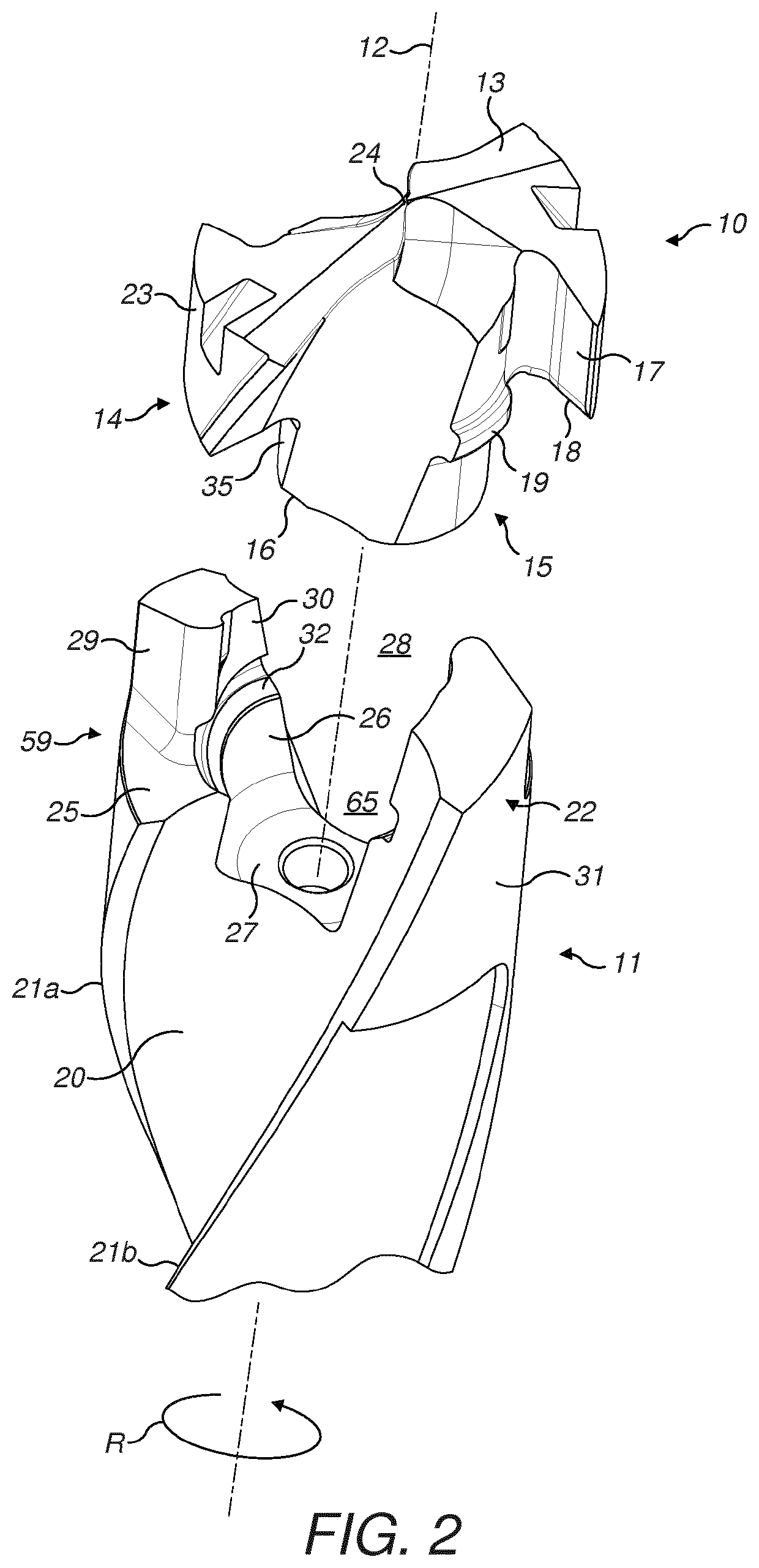
[0040]Referring to FIG. 2, insert 10 may be considered to comprise an axially forward head 14 being radially enlarged relative to a generally cylindrical central n...


PUM


Abstract

A cutting insert for a rotary drill tool and drill tool assembly in which an insert and a support body are coupled axially via a complementary shaped projection extending radially outward from the insert and received with a recess indented at a radially inward facing surface of the support body.

Description

FIELD OF INVENTION[0001]The present invention relates to a rotary drill tool insert and to a drill tool assembly in which the insert is mountable to a support body so as to maximise retention of the insert and keeping the insert centred on the support body whilst minimising stress and fatigue at the support body.BACKGROUND ART[0002]Multi-component drilling tool assemblies have been developed in which an insert formed from a hard expensive material (such as a cemented carbide, ceramic or the like) is releasably axially and radially locked at a tool or carrier body formed from a lower hardness and less expensive material. The insert is typically regarded as a wear part and is provided with an axially forward facing cutting region that typically includes a series of cutting edges and cutting surfaces.[0003]Control and management of the transmission of axial loading forces and torque from the insert to the drill body is required to securely mount the insert during use whilst enabling in...

Claims


Application Information

Patent Timeline
IPC IPC(8): B23B27/16
CPCB23B27/16B23B2251/02B23B2240/04B23B51/00B23B2240/32B23B2251/04B23B51/02B23B51/0005
Inventor PABEL, HELENAEKBACK, JOHAN
Owner SANDVIK INTELLECTUAL PROPERTY AB
Why Eureka
Try Eureka