Jaw crusher support frame

a support frame and jaw crusher technology, applied in the field of jaw crusher support frame, can solve the problems of compromising the structural integrity of the support frame, affecting the production efficiency of the crusher, affecting the quality of the crusher, etc., and achieves the effect of minimising the weight, facilitating the manufacture of the crusher support frame, and maximising the working strength of the fram

Pending Publication Date: 2019-10-17
SANDVIK INTELLECTUAL PROPERTY AB
View PDF0 Cites 2 Cited by
  • Summary
  • Abstract
  • Description
  • Claims
  • Application Information

AI Technical Summary

Benefits of technology

[0008]One objective of the present invention is to provide a jaw crusher support frame, typically referred to as a back frame end, which maximises the working strength of t

Problems solved by technology

On the one hand the crusher (and importantly its component parts) is required to be sufficiently robust to withstand significant loading forces in use whist on the other hand very heavy crushers are undesirable to manufacture, transport and maintain.
Conventionally, this reconfiguration is

Method used


Image

  • Jaw crusher support frame
  • Jaw crusher support frame
  • Jaw crusher support frame

Examples


Embodiment Construction

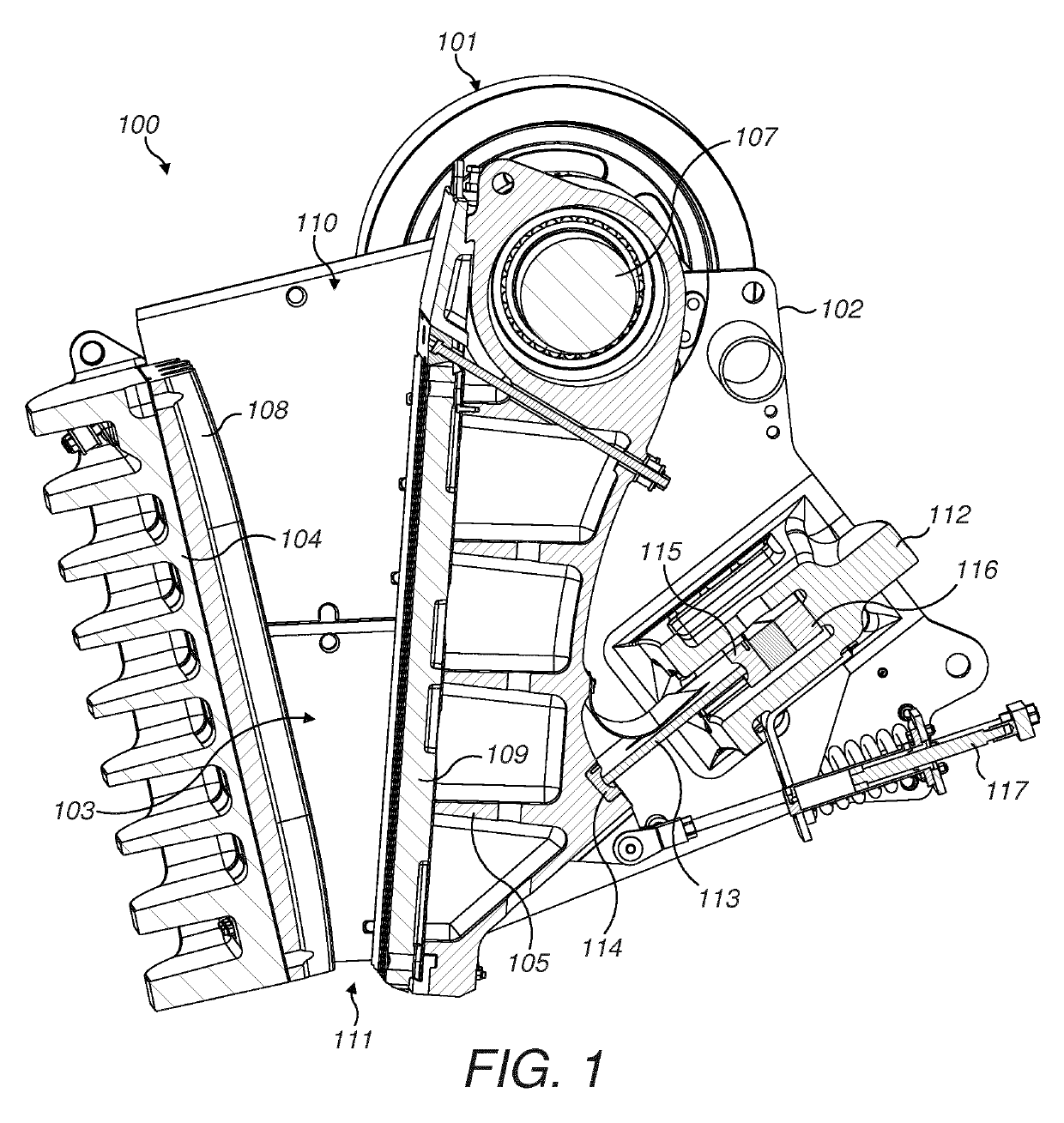
[0037]Referring to FIG. 1, a jaw crusher 100 comprises a main frame 102 mounting a movable jaw indicated generally by reference 105 and a fixed or stationary jaw indicated generally by reference 104. Movable jaw 105 is mounted eccentrically at a rotatable shaft 107 and is positioned separated and opposed to stationary jaw 104. A respective jaw plate 109 is mounted at movable jaw 105 and a corresponding jaw plate 108 is mounted at fixed jaw 104. A crushing zone indicated generally by reference 103 is defined between the opposed wear plates 109, 108 through which crushable material is allowed to fall. Jaws 104, 105 are arranged to be convergent towards their lower lengthwise ends such that an upper input end 110 of crushing zone 103 is enlarged relative to a lower discharge end 111. Material to be crushed is introduced into upper end 110, is crushed between jaw plates 108, 109 and is then discharge from lower end 111.

[0038]The gyratory oscillating movement of jaw 105 is controlled via...


PUM


Abstract

A jaw crusher having a movable jaw support frame configured to facilitate interchange between shim and wedge settings. The support frame is configured specifically to minimize stress concentrations and to provide the time efficient interchange between wedge and shim settings without a need to weld, cut and machine regions of the support frame.

Description

FIELD OF INVENTION[0001]The present invention relates to a jaw crusher support frame to support a movable jaw of a jaw crusher via a mechanically actuated link assembly and in particular, although not exclusively, to a jaw support frame configured to facilitate interchange between wedge and shim setting modes of operation.BACKGROUND ART[0002]Jaw crushers typically comprise a fixed jaw and a movable jaw that together define a crushing zone. A drive mechanism is operative to rock the movable jaw back and forth in order to crush material within this zone. The crushing zone is generally convergent towards its lower discharge end so that crushable material, fed to an upper and wider end of the zone, is capable of falling downward under gravity whilst being subject to repeated cycles of crushing movement in response to the cyclical motion of the movable jaw. The crushed material is then discharged under gravity through the lower and narrower discharge end onto a conveyor for onward proces...

Claims


Application Information

Patent Timeline
IPC IPC(8): B02C1/04B02C1/02B02C1/10
CPCB02C1/10B02C1/025B02C1/04B02C1/06
Inventor JOHANSSON, MARTINSJOBECK, ROGERKOTKAMAA, KIMLINDBERG, MARTEN
Owner SANDVIK INTELLECTUAL PROPERTY AB
Why Eureka
Try Eureka