LED fluorescent lamp

a fluorescent lamp and led technology, applied in the field of led fluorescent lamps, can solve the problem that led fluorescent lamps have not yet been widely distributed

Inactive Publication Date: 2017-04-20
KUMHO ELECTRIC INC +1
View PDF2 Cites 4 Cited by
  • Summary
  • Abstract
  • Description
  • Claims
  • Application Information

AI Technical Summary

Problems solved by technology

Thus, LED fluorescent lamps have not yet been widely distributed.

Method used


Image

  • LED fluorescent lamp
  • LED fluorescent lamp
  • LED fluorescent lamp

Examples


Embodiment Construction

[0054]The present invention will hereinafter be described in detail with reference to the accompanying drawings in which exemplary embodiments of the invention are shown.

[0055]Basic circuitries of electronic fluorescent lamp ballasts can generally be classified into a half bridge-type, an instant start-type and a program start-type. A conventional iron-core based magnetic ballasts can be classified into a starter type and a rapid start type. LED fluorescent lamps according to exemplary embodiments of the present invention can be applied to almost all types of fluorescent lamp ballasts. The structures of the LED fluorescent lamps according to the exemplary embodiments of the present invention and the operations of various types of fluorescent lamp ballasts to which the LED fluorescent lamps according to exemplary embodiments of the present invention are applied will hereinafter be described in detail.

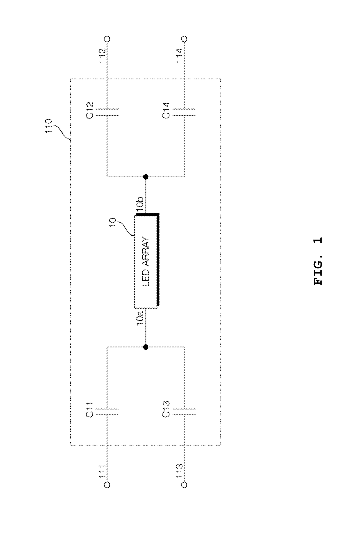
[0056]FIG. 1 illustrates a circuit diagram of an LED fluorescent lamp 110 according ...


PUM


Abstract

A light-emitting diode (LED) lamp which can replace a typical fluorescent lamp is provided. The LED lamp comprises external connection pins connected to terminals of an electronic or magnetic fluorescent lamp ballast, capacitor pairs connected to each of the external connection pins, diodes connected to each of the capacitor pairs and a LED array connected between the diodes, wherein an first external connection pin, a first capacitor pair, a first diode, an LED array, a second diode, a second capacitor pair and a second external connection pin are connected in series. Here, the first and second capacitor pairs include capacitors connected back to back. The LED lamp also further comprises a diode connected in anti-parallel with a series circuit of the second diode and the LED array, and another diode connected in anti-parallel with a series circuit of the first diode and the LED array.

Description

CROSS-REFERENCE TO RELATED APPLICATION[0001]This application is a continuation-in-part of U.S. application Ser. No. 14 / 717,428 filed on May 20, 2015, which is a continuation of U.S. application Ser. No. 14 / 145,420, filed on Dec. 31, 2013, which is a continuation-in-part of U.S. application Ser. No. 13 / 708,572 filed on Dec. 7, 2012, which is a continuation of U.S. application Ser. No. 12 / 473,098 filed on May 27, 2009. This application also claims the benefit of Korean Patent Application No. 10-2008-0101413 filed on Oct. 16, 2008, No. 10-2008-0109048 filed on Nov. 4, 2008, No. 10-2008-0123444 filed on Dec. 5, 2008, and No. 10-2009-0018268 filed on Mar. 4, 2009 in the Korean Intellectual Property Office, the disclosures of which are expressly incorporated by reference in their entireties.BACKGROUND OF THE INVENTION[0002]1. Field of the Invention[0003]The present invention relates to a light-emitting diode (LED) fluorescent lamp, and more particularly, to an LED fluorescent lamp which i...

Claims


Application Information

Patent Timeline
Patent Type & Authority Applications(United States)
IPC IPC(8): F21K9/278H05B33/08H05B44/00
CPCF21K9/278H05B33/0845F21Y2115/10H05B33/089H05B33/0815H05B45/40H05B45/50H05B45/3578Y02B20/30H05B45/39H05B45/59
Inventor PARK, MYUNG KOO
Owner KUMHO ELECTRIC INC
Why Eureka
Try Eureka