Door hinge

Inactive Publication Date: 2017-04-27
HSCC LTD
View PDF1 Cites 2 Cited by
  • Summary
  • Abstract
  • Description
  • Claims
  • Application Information

AI Technical Summary

Benefits of technology

The invention provides a door hinge with a rotational bearing and a hydraulic dampener. The rotational bearing can lift the first armature part when the second armature part is opened, and the hydraulic dampener can reduce the movement of the second armature part when the hinge is closed. This enhances the smooth operation of the door hinge and improves the stability of the door.

Problems solved by technology

The disadvantage of current designs is that these kind of doors shut very abruptly due to their weight, which results in high stress on the door and bears the risk of injury.

Method used


Image

  • Door hinge
  • Door hinge
  • Door hinge

Examples


first embodiment

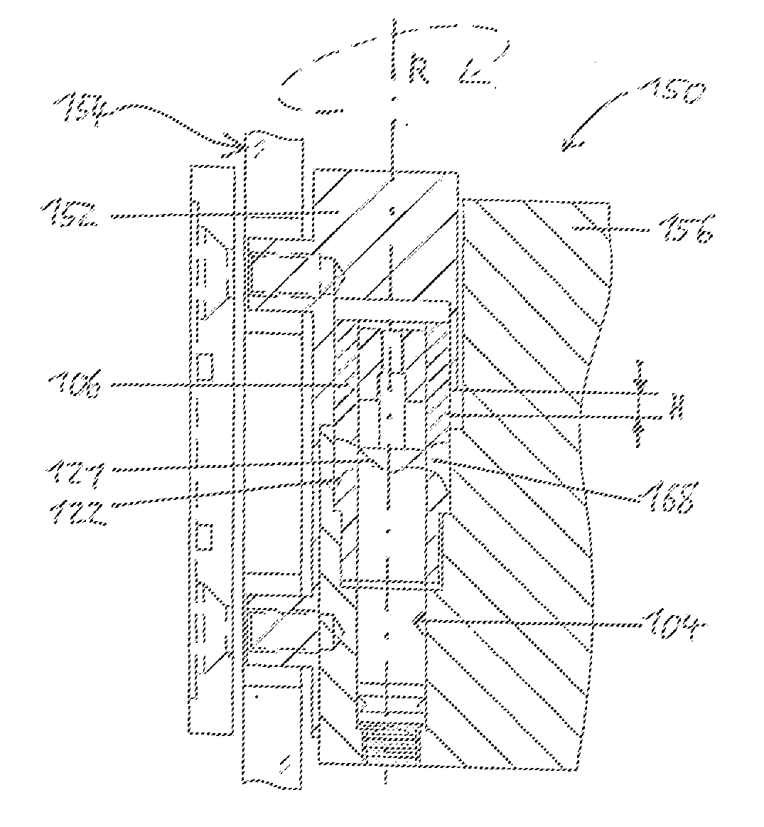
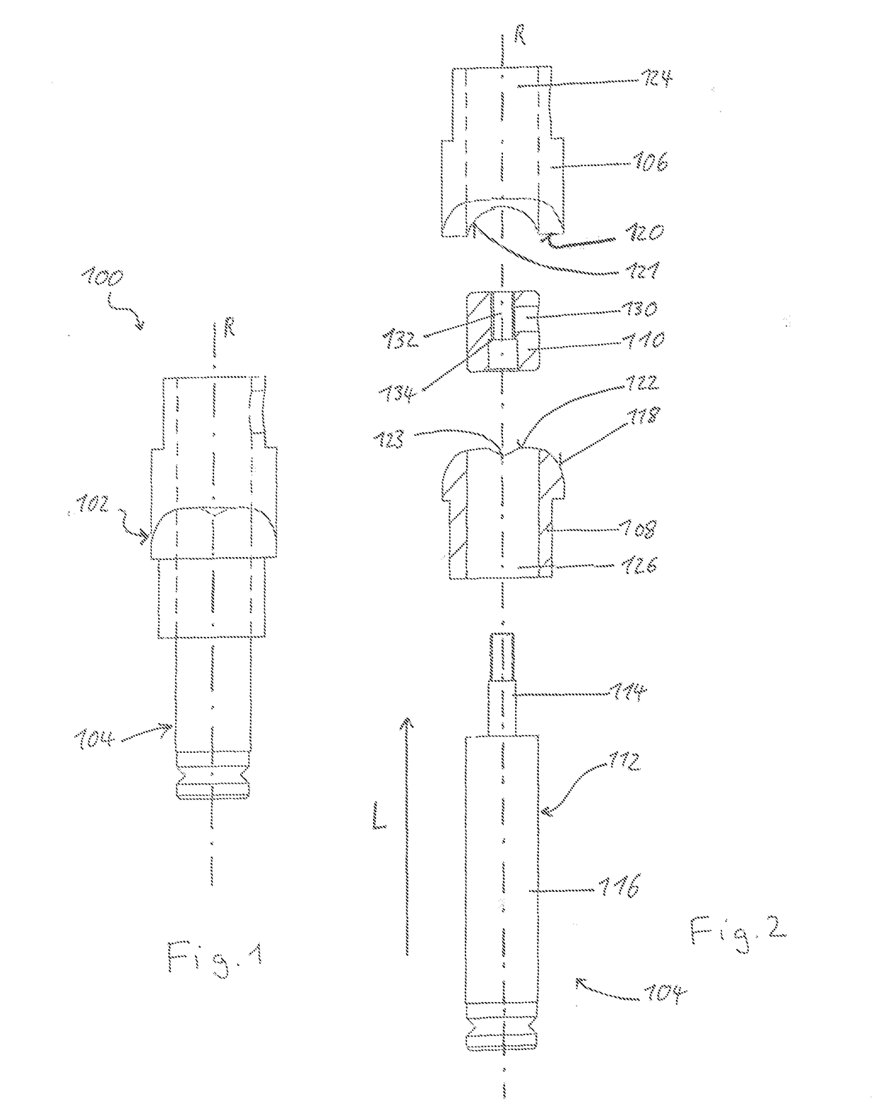
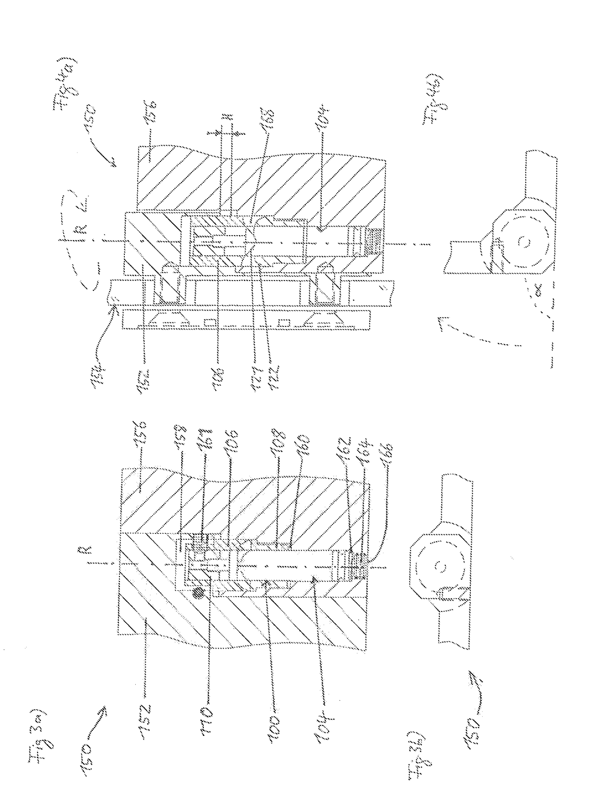
[0038]In FIG. 1 and 2, a hinge bearing unit 100 according to the invention is shown. The hinge bearing unit 100 comprises a rotational bearing 102 and a hydraulic dampener 104 which are arranged coaxially to the hinge axis R.

[0039]The rotational bearing 102 comprises a first, upper bearing part 106, a second, lower bearing part 108 which both comprise a sleeve portion, and a plug 110 which defines a first front wall closing bearing part 106.

[0040]The hydraulic dampener 104 has an elongated, preassembled piston-cylinder unit 112 with a piston rod end 114 which protrudes from the cylinder 116 and is resiliently pushed in direction L by the pressure within the cylinder 116.

[0041]The first bearing part 106 and the second bearing part 108 feature front surfaces 118, 120 (here: ring-shaped front surfaces) which are opposing each other and are, at least in sections, complementary as well as contacting each other.

[0042]In this embodiment, each of the front surfaces 118, 120 defines a cam su...

second embodiment

[0061]FIG. 5 illustrates the present invention, wherein the hinge bearing unit 200 comprises a rotational bearing 202 and at least one (here two) hydraulic dampener 212 which is arranged perpendicular to the hinge axis R.

[0062]The rotational bearing 202 is formed by a bearing rod 206 which features a section 208 with a non-circular cylindrical circumferential surface 210 defining a cam 211 having portions with different distances from the hinge axis R.

[0063]The hydraulic dampeners 212 are two identical units which are arranged parallel to each other. Each unit comprises an elongated, preassembled piston-cylinder unit 212 with a piston rod end 214 which protrudes from a cylinder 216. A spring 218 through which the piston rod end 214 extends and a head part 220 attached to the outer free piston rod end 214 are for urging against the cam 211 in order to self-close the door by the force of the springs.

[0064]The spring 218 extends between the head part 220 and the cylinder 216 and pulls ...

third embodiment

[0076]FIG. 8a) illustrates the present invention, wherein the hinge bearing unit 300 comprises a rotational bearing 302 and a hydraulic dampener 304 which are arranged coaxially to the hinge axis R.

[0077]The rotational bearing 302 comprises a first, upper bearing part 306 and a second, lower bearing part 308 which comprises a sleeve portion.

[0078]The hydraulic dampener 304 has an elongated, preassembled piston-cylinder unit 312 with a piston rod end 314 which protrudes from the cylinder 316 and is resiliently pushed in direction L by the pressure within the cylinder 316 (see FIG. 8b).

[0079]The first bearing part 306 features a section with a surface 318 in the form of a female thread 321 aligned with the hinge axis R and the second bearing part 308 features a section with a surface 320 in the form of a corresponding male thread 322, so that the first bearing part 306 and the second bearing part 308 are coupled to each in the direction of the hinge axis R by the threads 321, 322.

[008...


PUM


Abstract

A door hinge comprises a hinge axis (R), a first armature part for attachment to a door, a second armature part for attachment to a wall, pivotably coupled with the first armature part, a rotational bearing having a first bearing part coupled to the first armature part and a second bearing part coupled to the second armature part, the rotational bearing comprising at least one surface for lifting the first armature part relative to the second armature part upon rotating the second armature part from a closed to an open position, and a hydraulic dampener integrated into the rotational bearing for dampening the lowering movement of the second armature part when pivoting the hinge in a closed position.

Description

BACKGROUND OF THE INVENTION[0001]The term door relates to all elements featuring hinges which can be used to close an opening, e.g. doors, flaps, hatches, etc.[0002]Door hinges are well known. Apart from very basic designs, there are a variety of more sophisticated door hinges that feature additional functions. One such feature is a door that is lifted when the door is swiveled opened around its hinge and closes autonomously due to its weight.[0003]The disadvantage of current designs is that these kind of doors shut very abruptly due to their weight, which results in high stress on the door and bears the risk of injury.[0004]The object of the present invention is to provide a door hinge that dampens the force with which the door slams shut, in this way softening the closing of the door.SUMMARY OF THE INVENTION[0005]To achieve this object, the invention provides a door hinge, comprising a hinge axis, a first armature part for attachment to a door, a second armature part for attachmen...

Claims


Application Information

Patent Timeline
IPC IPC(8): E05F5/02E05D11/10E05D3/02
CPCE05F5/027E05D3/022E05Y2900/114E05D2700/04E05D11/10E05F3/20
Inventor JEANROT, JUERGEN
Owner HSCC LTD
Why Eureka
Try Eureka