
Well drilling apparatus and method of use

a technology for drilling equipment and wells, applied in the direction of earth drilling tools, borehole/well accessories, construction, etc., can solve the problems of heavy and cumbersome handling equipment, insufficient solutions for hand drilling of wells, and the weight of existing tools that are necessary for drilling into the earth

Active Publication Date: 2017-04-27
CRAWFORD III RUSSELL C
View PDF0 Cites 2 Cited by
  • Summary
  • Abstract
  • Description
  • Claims
  • Application Information

AI Technical Summary

Benefits of technology

The invention is a well-drilling apparatus that can be used by individuals or attached to a power unit. It uses a lightweight drill stem that floats within the borehole using buoyancy, which eliminates the need for heavy drilling tools. The apparatus can adjust for drilling conditions by anticipating strata and locating drilling discharge ports for better penetration rates. Overall, the apparatus provides a simple and effective way to drill wells.

Problems solved by technology

Currently, existing technology does not provide sufficient solutions for the drilling of wells by hand.
A key deficiency includes the weight of existing tools that are necessary for drilling into the earth.
Typically, the tools used for drilling are comprised of heavy metal and therefore require use of heavy and cumbersome handling equipment.
In addition, a further issue is that using existing technology, the reverse flow process requires that the rate of discharge of drilling fluid and the rate of introduction of air needs to be adjusted for varying conditions.
For example, at shallow depths, the air lift reverse flow process is not efficient with respect to the materials that are being drilled.
This may frequently lead to problems with regard to the penetration rate of the drill and to the plugging of the discharge port from which cuttings may be expelled from the drill stem.

Method used


Image

  • Well drilling apparatus and method of use
  • Well drilling apparatus and method of use
  • Well drilling apparatus and method of use

Examples


Embodiment Construction

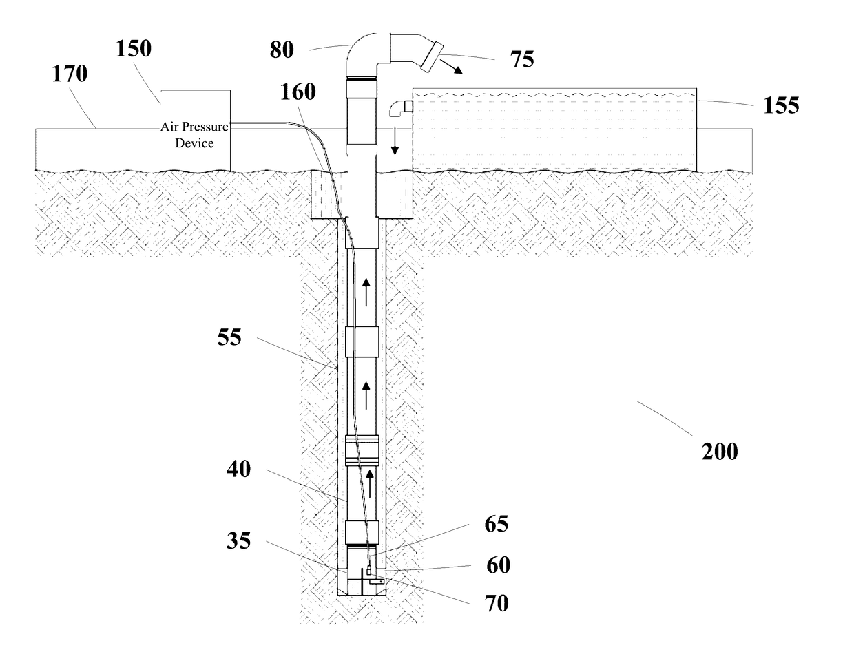
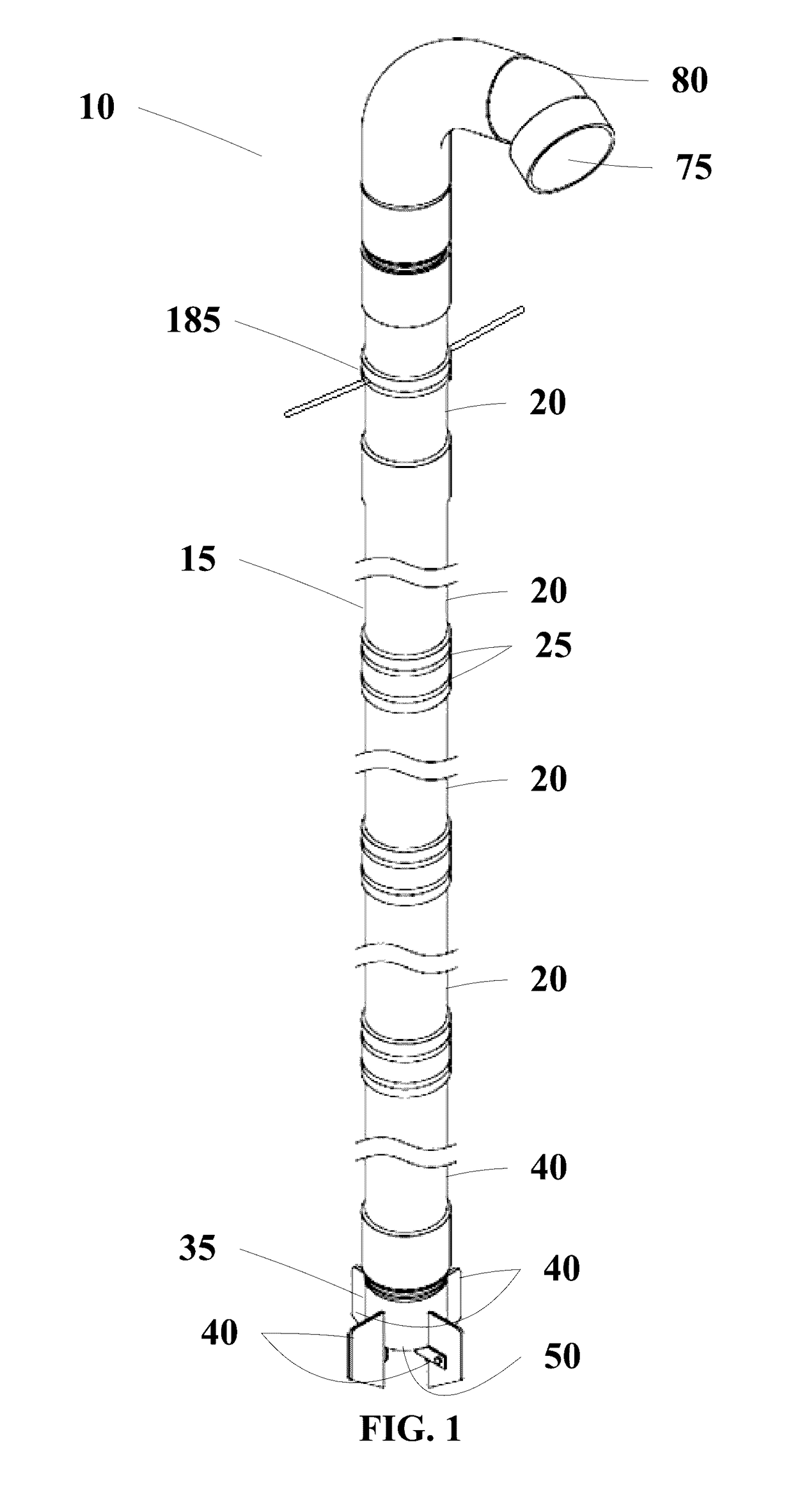
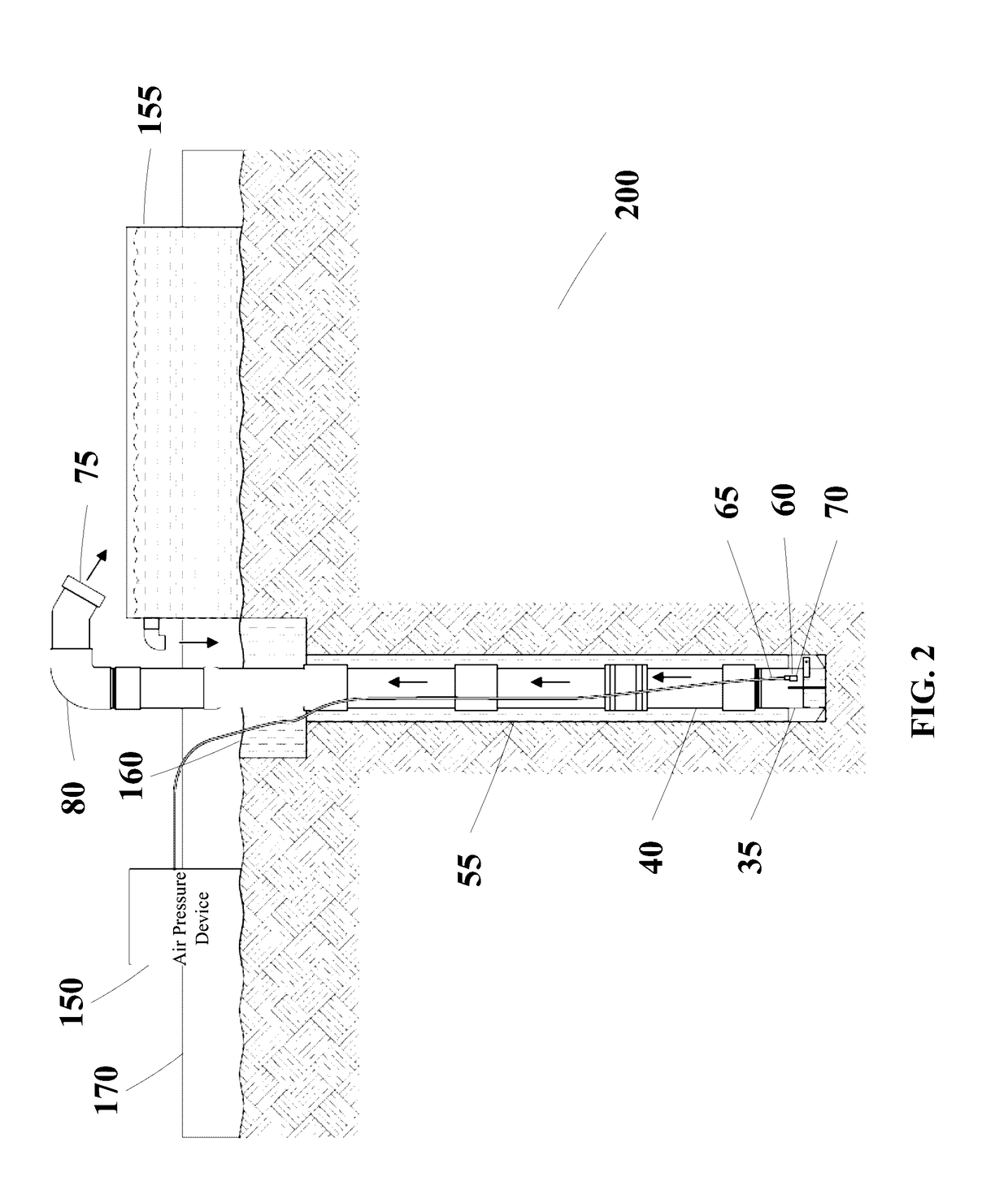
[0017]Reference now should be made to the drawings, in which the same reference numbers are used throughout the different figures to designate the same components.

[0018]It will be understood that, although the terms first, second, third, etc. may be used herein to describe various elements, these elements should not be limited by these terms. These terms are only used to distinguish one element from another element. Thus, a first element discussed below could be termed a second element without departing from the teachings of the present disclosure.

[0019]The terminology used herein is for the purpose of describing particular embodiments only, and is not intended to be limiting. As used herein, the singular forms “a”, “an”, and “the” are intended to include the plural forms as well, unless the context clearly indicates otherwise. It will be further understood that the terms “comprises” and / or “comprising” or “includes” and / or “including” when used in this specification, specify the pr...


PUM


Abstract

Embodiments provide a well-drilling apparatus and a method of use.

Description

CROSS-REFERENCE TO RELATED APPLICATIONS[0001]This application claims priority to U.S. Provisional Patent Application 62 / 246,631, filed Oct. 27, 2015, which is hereby incorporated by reference in its entirety.FIELD OF THE INVENTION[0002]The present disclosure relates to a well-drilling apparatus and its method of use. Embodiments relate to a well-drilling apparatus which may be operable by hand or by mechanical means.BACKGROUND OF THE INVENTION[0003]Currently, existing technology does not provide sufficient solutions for the drilling of wells by hand. A key deficiency includes the weight of existing tools that are necessary for drilling into the earth. Typically, the tools used for drilling are comprised of heavy metal and therefore require use of heavy and cumbersome handling equipment.[0004]In addition, a further issue is that using existing technology, the reverse flow process requires that the rate of discharge of drilling fluid and the rate of introduction of air needs to be adj...

Claims


Application Information

Patent Timeline
Patent Type & Authority Applications(United States)
IPC IPC(8): E21B21/08E21B21/01E21B11/00
CPCE21B21/08E21B21/01E21B11/005E21B21/103E21B21/16E21B21/12E21B10/60E21B43/10
Inventor CRAWFORD, III, RUSSELL C.
Owner CRAWFORD III RUSSELL C
Learn More