Absorbent structure

a technology of absorbent pads and absorbent pads, applied in the field of absorbent pads, can solve the problems of less secure storage and reduced equilibrium pressur

Active Publication Date: 2017-05-04
THE PROCTER & GAMBLE COMPANY
View PDF4 Cites 69 Cited by
  • Summary
  • Abstract
  • Description
  • Claims
  • Application Information

AI Technical Summary

Benefits of technology

[0008]An absorbent structure comprising a single stratum exhibiting a Capillarity Work Potential for a fixed permeability that is greater than the Capillarity Work Potential trade-off Boundary and less than 20 times the Capillary Work Potential trade-off; and a permeability greater than the Capillarity Work Potential trade-off Boundary for a given Capillary Work Potential is also described.

Problems solved by technology

This is shown as reduced equilibrium pressure (which in the case of absorbent products translates to lower rewet pressure and hence less secure storage).

Method used


Image

  • Absorbent structure
  • Absorbent structure
  • Absorbent structure

Examples


examples

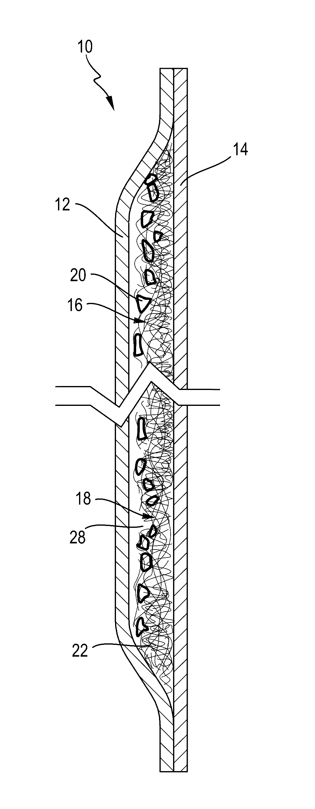
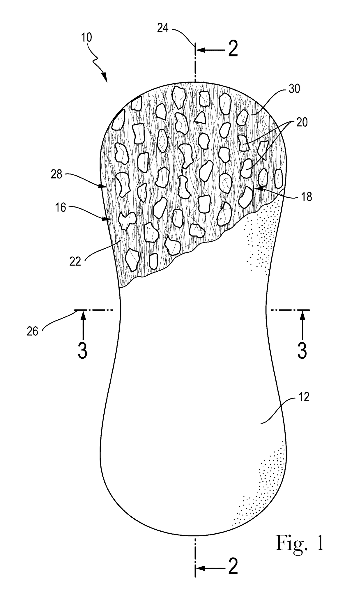
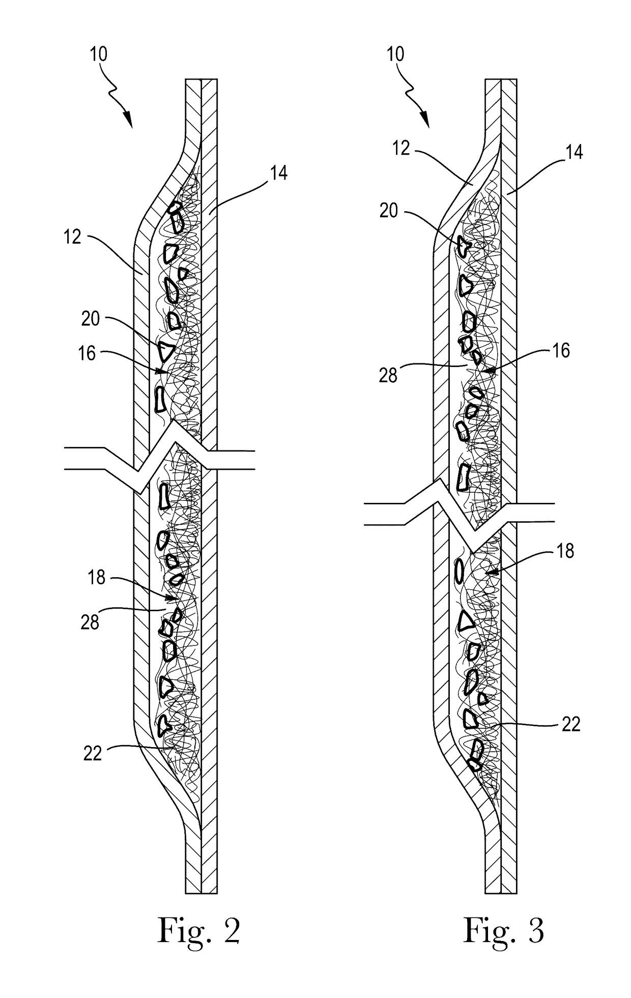
[0184]A. An absorbent structure comprising a single stratum exhibiting a Capillarity Work Potential greater than the Capillarity Work Potential trade-off Boundary.[0185]B. The absorbent structure according to paragraph A, wherein the absorbent structure comprises a heterogeneous mass comprising enrobeable elements and one or more pieces of open-cell foam.[0186]C. The absorbent structure according to paragraph A or B, wherein the absorbent structure exhibits a Capillary Work Potential of between 100 mJ / m2 and 10,000 mJ / m2 and a permeability between 10 Darcy and 10,000 Darcy.[0187]D. The absorbent structure according to any of paragraphs A-C, wherein the absorbent structure exhibits a Capillary Work Potential of between 1,000 mJ / m2 and 10,000 mJ / m2 and a permeability between 10 Darcy and 10,000 Darcy.[0188]E. The absorbent structure according to any of paragraphs A-D, wherein the absorbent structure exhibits a Capillary Work Potential of between 1,000 mJ / m2 and 10,000 mJ / m2 and a perm...


PUM

PropertyMeasurementUnit
sizeaaaaaaaaaa
sizeaaaaaaaaaa
sizeaaaaaaaaaa

Abstract

An absorbent structure comprising a single stratum exhibiting a Capillarity Work Potential greater than the Capillarity Work Potential trade-off Boundary.

Description

FIELD OF THE INVENTION[0001]The present invention relates to absorbent structures useful in absorbent articles such as diapers, incontinent briefs, training pants, diaper holders and liners, sanitary hygiene garments, and the like. Specifically, the present invention relates to an absorbent structure that exhibits desirable consumer properties.BACKGROUND OF THE INVENTION[0002]Absorbent articles for the absorption of fluids aim to rapidly absorb fluids so that they are not left in contact with the user. Conventional Porous Media (PM) structures and super absorbent polymers (SAP) utilized as acquisition and storage layers in the hygiene product industry show a known trade-off between driving force for fluid acquisition (capillary suction) and resistance to the flow (inverse of permeability). This is due to the underlying physics behind flow into the desired material, which can be effectively described by statistical percolation theories.[0003]Ultimately, the material structure is resp...

Claims


Application Information

Patent Timeline
Patent Type & Authority Applications(United States)
IPC IPC(8): A61F13/15A61F13/53
CPCA61F13/15203A61F13/53A61F2013/530817A61F2013/530233A61F2013/530007A61F2013/530379A61F2013/15544A61L15/28A61F13/15
Inventor BEWICK-SONNTAG, CHRISTOPHER PHILIPCARLA, VITOHUBBARD, JR., WADE MONROEHAMMONS, JOHN LEE
Owner THE PROCTER & GAMBLE COMPANY
Why Eureka
Try Eureka