
Stackable support system and method

a support system and support plate technology, applied in the direction of sealing/packing, wellbore/well accessories, earthwork drilling and mining, etc., can solve the problems of limited contact area and load capacity, and achieve the effect of reducing the number of screws

Active Publication Date: 2017-05-04
ONESUBSEA IP UK LTD
View PDF1 Cites 5 Cited by
  • Summary
  • Abstract
  • Description
  • Claims
  • Application Information

AI Technical Summary

Benefits of technology

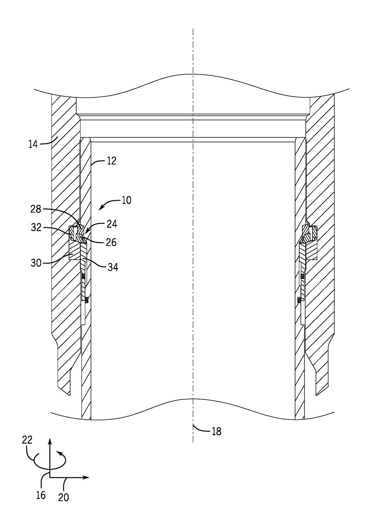
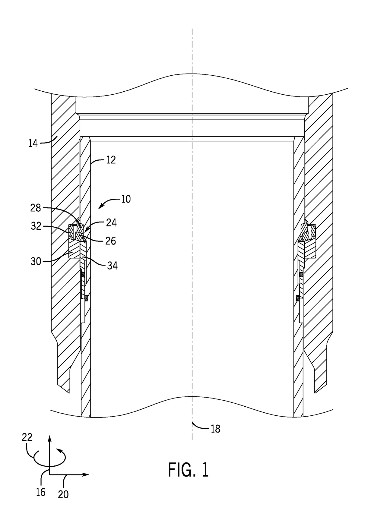
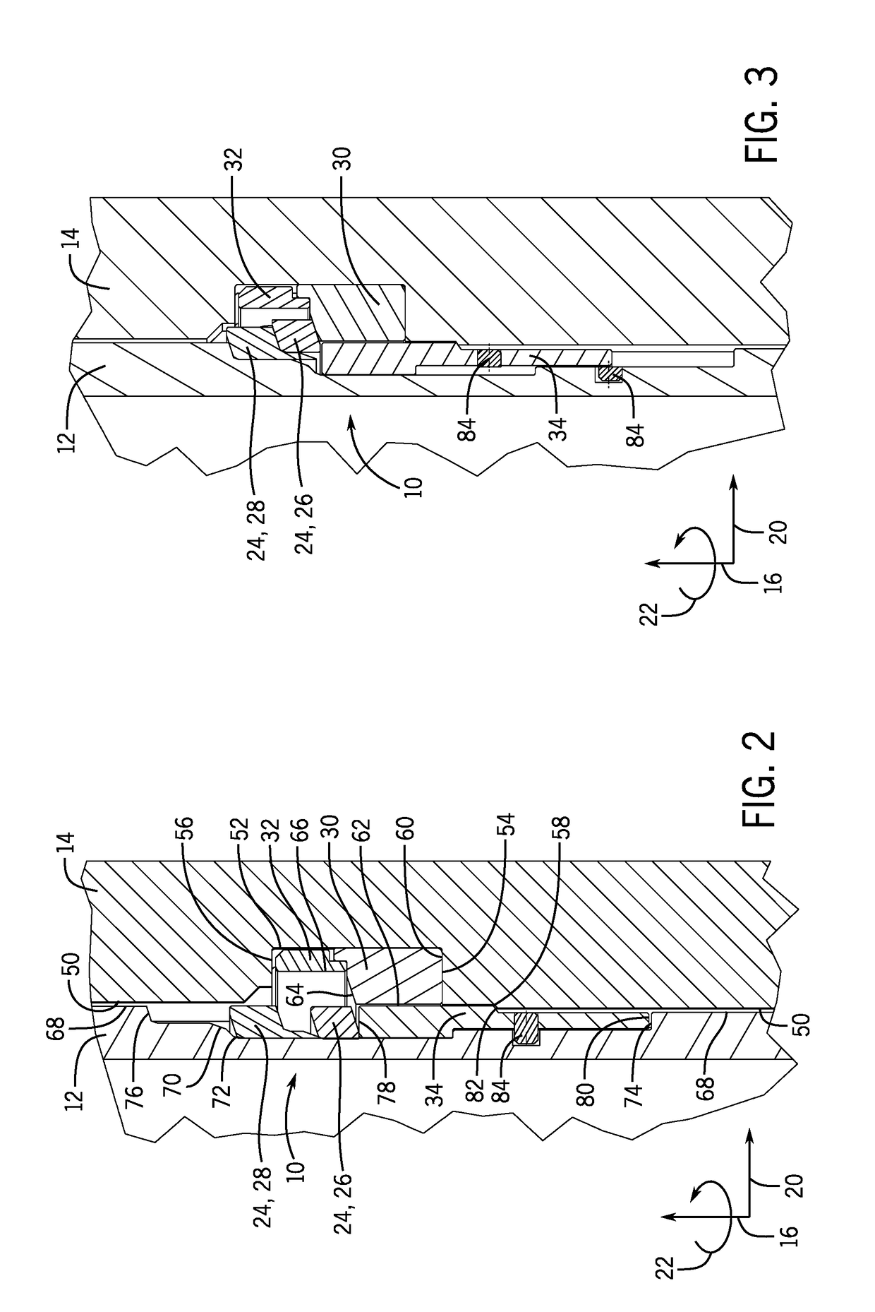
This patent is about a system for installing a body in a receptacle. The system includes a load shoulder that is supported by and in a fixed position with respect to the receptacle. There is also an actuator that is supported by and in a fixed position with respect to the receptacle. The body is designed to move with respect to the receptacle, and when the body moves, the top lock component and the bottom lock component move to lock the body in close alignment with the receptacle. The technical effect of this system is to provide a reliable and secure way to install a body in a receptacle.

Problems solved by technology

However, in all of the above examples, the extent of split lock ring expansion, and thus the contact area and load capacity, typically is limited by the inner and outer diameters of the mating cylinders, such that one must be able to pass through the other.

Method used


Image

  • Stackable support system and method
  • Stackable support system and method
  • Stackable support system and method

Examples


Embodiment Construction

[0017]One or more specific embodiments of the present disclosure will be described below. These described embodiments are only exemplary of the present invention. In an effort to provide a concise description of these embodiments, all features of an actual implementation may not be described in the specification. It should be appreciated that in the development of any such actual implementation, as in any engineering or design project, numerous implementation-specific decisions must be made to achieve the developers' specific goals, such as compliance with system-related and business-related constraints, which may vary from one implementation to another. Moreover, it should be appreciated that such a development effort might be complex and time-consuming, but would nevertheless be a routine undertaking of design, fabrication, and manufacture for those of ordinary skill having the benefit of this disclosure.

[0018]This discussion is directed to various embodiments of the disclosure. T...


PUM


Abstract

A stackable support system and method are disclosed to increase the final contact area of an expanding lock component by stacking one ring on top of another such that one ring acts as an actuator for the one beneath it. As a body lands inside a receptacle, e.g. a narrow cylinder lands inside a larger cylinder, the components or rings expand in a domino effect, resulting in a greater contact between the body and receptacle than would occur if there was only one component or ring. The stackable support system includes a number of expandable lock rings which stack on top of each other. These rings, when expanded, steadily increase in diameter, resulting in an overall larger surface on the bottom of the support system than could have been achieved with one ring.

Description

CROSS-REFERENCE TO RELATED APPLICATIONS[0001]This application claims priority to and the benefit of U.S. Provisional Application No. 62 / 250,975, filed Nov. 4, 2015, and entitled “Stackable Support System and Method,” the disclosure of which is incorporated by reference in its entirety for all purposes.BACKGROUND[0002]This section is intended to introduce the reader to various aspects of art that may be related to various aspects of the presently described embodiments. This discussion is believed to be helpful in providing the reader with background information to facilitate a better understanding of the various aspects of the described embodiments. Accordingly, it should be understood that these statements are to be read in this light and not as admissions of prior art.[0003]In the oil and gas industry, a well may be drilled and a completion system may be installed at a surface end of the well in order to extract oil, natural gas, and / or other subterranean resources from the earth. ...

Claims


Application Information

Patent Timeline
Patent Type & Authority Applications(United States)
IPC IPC(8): E21B33/04
CPCE21B33/04E21B23/02
Inventor COOKSTON, CHRISTOPHER JOHN
Owner ONESUBSEA IP UK LTD
Learn More