Vehicle display device, display control method, and rearview monitoring system

Active Publication Date: 2017-05-11
SONY CORP
View PDF12 Cites 33 Cited by
  • Summary
  • Abstract
  • Description
  • Claims
  • Application Information

AI Technical Summary

Benefits of technology

[0011]According to one or more embodiments of the present technology, an image depicting the area around a vehicle is displayed on a display unit that is installed in the cabin of the vehicle and whose display face is oriented in a different direction from the direction of the driver. A mirror unit is installed in the cabin of the vehicle and reflects some or all of the image area displayed on the display unit. The visible range of the surrounding area that is visible to the driver through the image of the display unit reflected in the mirror unit changes according to mov

Problems solved by technology

However, with a monitoring system that simply displays an image acquired with an image capture device on a display device, the visib

Method used


Image

  • Vehicle display device, display control method, and rearview monitoring system
  • Vehicle display device, display control method, and rearview monitoring system
  • Vehicle display device, display control method, and rearview monitoring system

Examples


first embodiment

1-2. Operation of First Embodiment

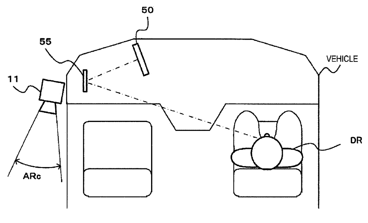
[0076]FIG. 6 is a diagram for explaining operation of a first embodiment. The display unit 50 displays a captured image that has been captured by the surrounding area image capture unit 11. The mirror unit 55 is configured as a planar mirror, for example, and sized so that a partial area GRm of the display area GRc of the display unit 50 is visible when the driver DR indirectly views a captured image of the surrounding area via the mirror unit 55. Note that the area GRm is designated the monitor image area. Also, the display unit 50 displays an image of the area ARc captured by the surrounding area image capture unit 11 in the display area GRc.

[0077]The display unit 50 and the mirror unit 55 are arranged so that when the driver DR of the vehicle moves his or her head position to change the visible range, such as by moving in the direction of the arrow Va, for example, the monitor image area GRm that is visible via the mirror unit 55 moves in the dir...

second embodiment

2-2. Operation of Second Embodiment

[0098]FIG. 11 is a diagram for explaining operation of a second embodiment. The display controller 20 displays an image of the area ARc captured by the surrounding area image capture unit 11 in the display area GRc of the display unit 50. The mirror unit 55 is configured as a planar mirror, for example, and sized so that the display area GRc of the display unit 50 is visible when the driver DR indirectly views a captured image of the surrounding area via the mirror unit 55.

[0099]In addition, the display controller 20 conducts a brightness control, compression process, and the like on the display image in the display area GRc, and presents a display in the display area GRc that distinguishably displays an image of the visible range, which is the range of the surrounding area visible to the driver via the mirror unit 55. Herein, the display area corresponding to the visible range is designated the monitor image area GRm.

[0100]Furthermore, the display...

third embodiment

3-2. Operation of Third Embodiment

[0141]FIG. 19 is a flowchart illustrating operation of a display controller in the third embodiment. In step ST11, the display controller 20 determines whether or not an operation of checking the surrounding area has been performed. The display controller 20, on the basis of an image signal supplied from the driver image capture unit 12, determines whether or not the driver's head orientation and line of sight direction are in the direction of the mirror unit 55, for example. If the driver's head orientation and line of sight direction are in the direction of the mirror unit 55, such as when the driver glances in the direction of the mirror unit 55, for example, the display controller 20 determines that an operation of checking the surrounding area has been performed, and proceeds to step ST12. Meanwhile, if the driver's head orientation and line of sight direction are not in the direction of the mirror unit 55, the display controller 20 determines ...


PUM


Abstract

Vehicle display device (10) including a display unit (50), installed in a cabin of a vehicle and having a display face oriented in a different direction from a direction of a driver (DR), configured to display an image depicting a surrounding area of the vehicle, and a mirror unit (55) installed in the cabin of the vehicle and configured to reflect some or all of an image area displayed on the display unit (50). A visible range of the surrounding area visible to the driver through an image of the display unit (50) reflected in the mirror unit (55) changes according to movement of a viewing position of the driver (DR) with respect to the mirror unit (55).

Description

CROSS REFERENCE TO RELATED APPLICATIONS[0001]This application claims the benefit of Japanese Priority Patent Application JP 2014-164179 filed Aug. 12, 2014, the entire contents of which are incorporated herein by reference.TECHNICAL FIELD[0002]The present technology relates to a vehicle display device, a display control method, and a rearview monitoring system, and enables easy viewing of the area around a vehicle.BACKGROUND ART[0003]Recently, functions corresponding to the rearview mirror of a vehicle are being realized by a monitoring system made up of an image capture device and a display device. With a viewing method using a rearview mirror, a driver is able to move the range that may be viewed (hereinafter designated the “visible range”) by moving his or her head, eye position, or the like (hereinafter simply designated the “head position”). However, with a monitoring system that simply displays an image acquired with an image capture device on a display device, the visible ran...

Claims


Application Information

Patent Timeline
IPC IPC(8): B60R1/08H04N7/18B60R1/12
CPCB60R1/08B60R1/12H04N7/181B60R2001/1215B60R2300/8046B60R2300/105B60R2300/306B60R2300/70B60R2001/1253B60R1/00B60R2300/303
Inventor OBA, EIJI
Owner SONY CORP
Why Eureka
Try Eureka