
Control equipment

a technology of control equipment and helical transmission, which is applied in the direction of valve operating means/releasing devices, valves, gearing, etc., can solve the problems of complex design large space occupation large number of individual parts of known actuation devices, etc., to achieve efficient and direct force transmission of rotation, efficient and robust helical transmission, and simple, rapid and/or inexpensive manufacturing

Active Publication Date: 2017-05-18
FESTO AG & CO KG
View PDF9 Cites 0 Cited by
  • Summary
  • Abstract
  • Description
  • Claims
  • Application Information

AI Technical Summary

Benefits of technology

This actuation device has the advantage of being able to open up new possibilities for the spatial arrangement of parts, resulting in smaller dimensions and improved stability. The device is made up of simple parts that can be manufactured with a large tolerance and is easy to assemble, repair, and service. The device also allows for several small movements to be executed in a sequential manner, which prevents seizures and slows down the development of encrustation. Overall, this device provides a compact, stable, and cost-effective solution for transmitting power in various applications.

Problems solved by technology

The design of known actuation devices, however, is complicated and such devices turn out to be spatially quite large, on account of the hitherto existing construction manner, which realises a coupling of the rotational drive movement to the rotational movement of the drive output by way of gearwheel transmissions, chains and / or belts.
Moreover, known actuation devices can include many individual parts and / or small, precisely manufactured parts and are expensive in manufacture, assembly, maintenance and repair.
Moreover, known actuation devices can be quite prone to malfunctioning, can greatly wear and / or can be difficult to assemble, to service or to repair.

Method used


Image

  • Control equipment
  • Control equipment
  • Control equipment

Examples


Embodiment Construction

[0121]Basically in the figures, the same parts are provided with the same reference numerals.

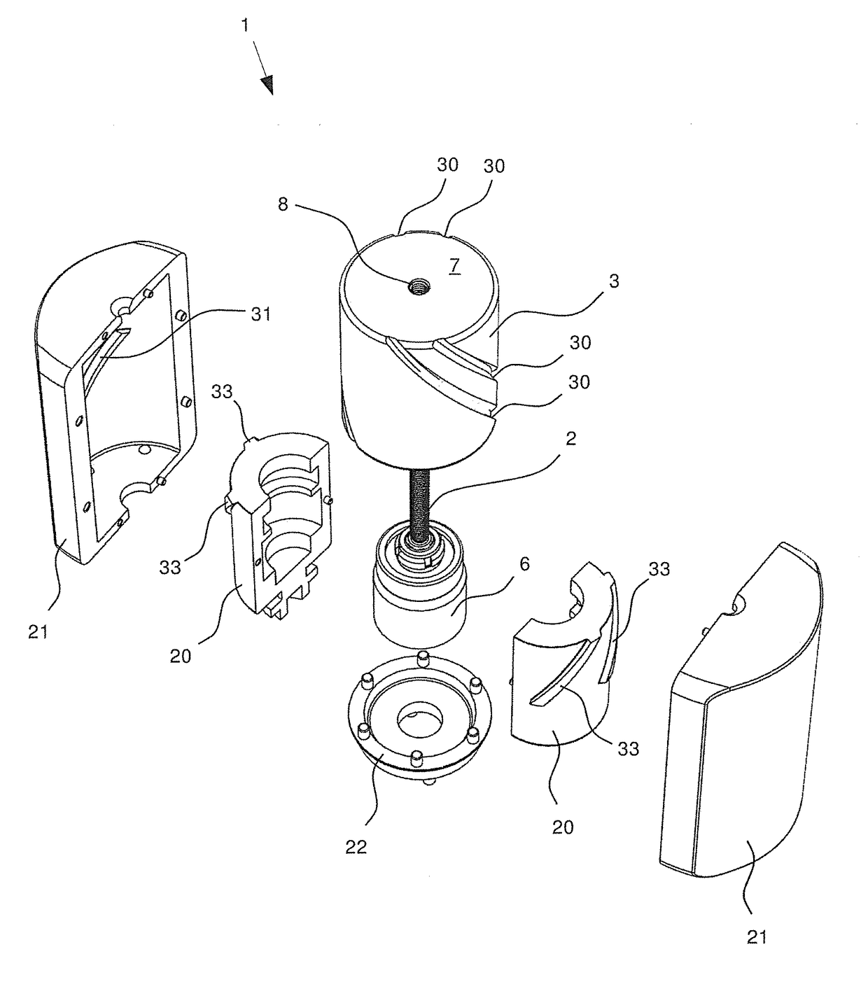
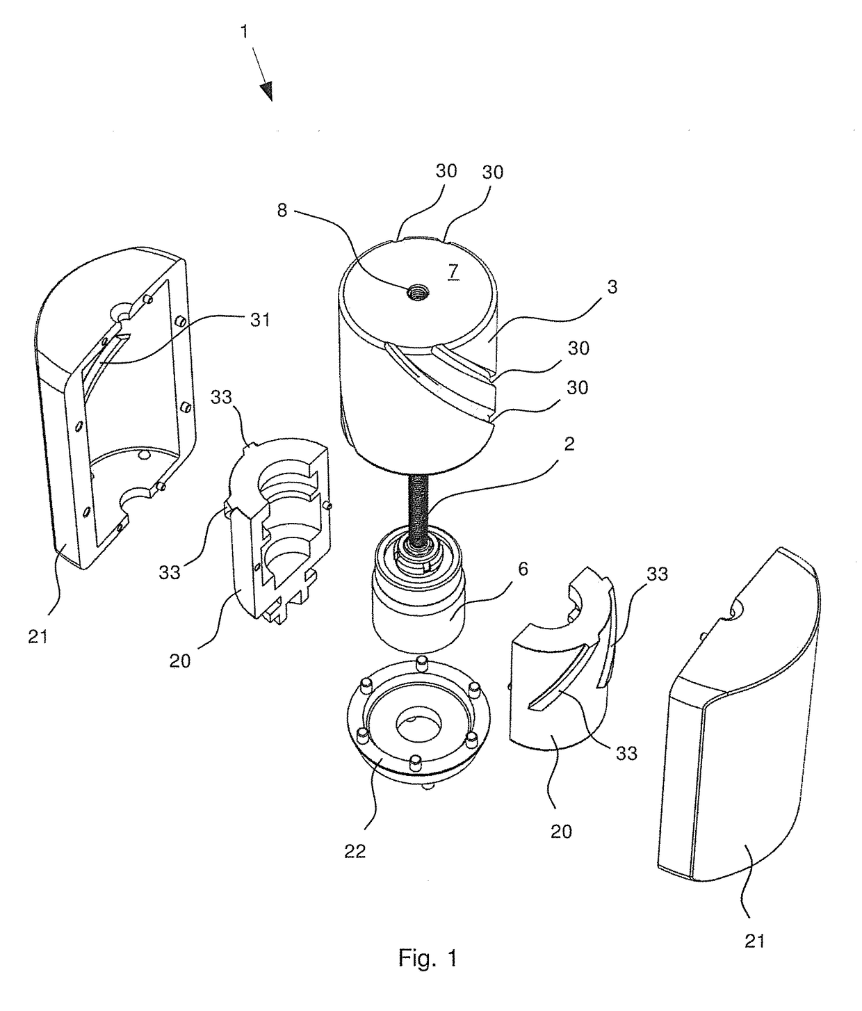
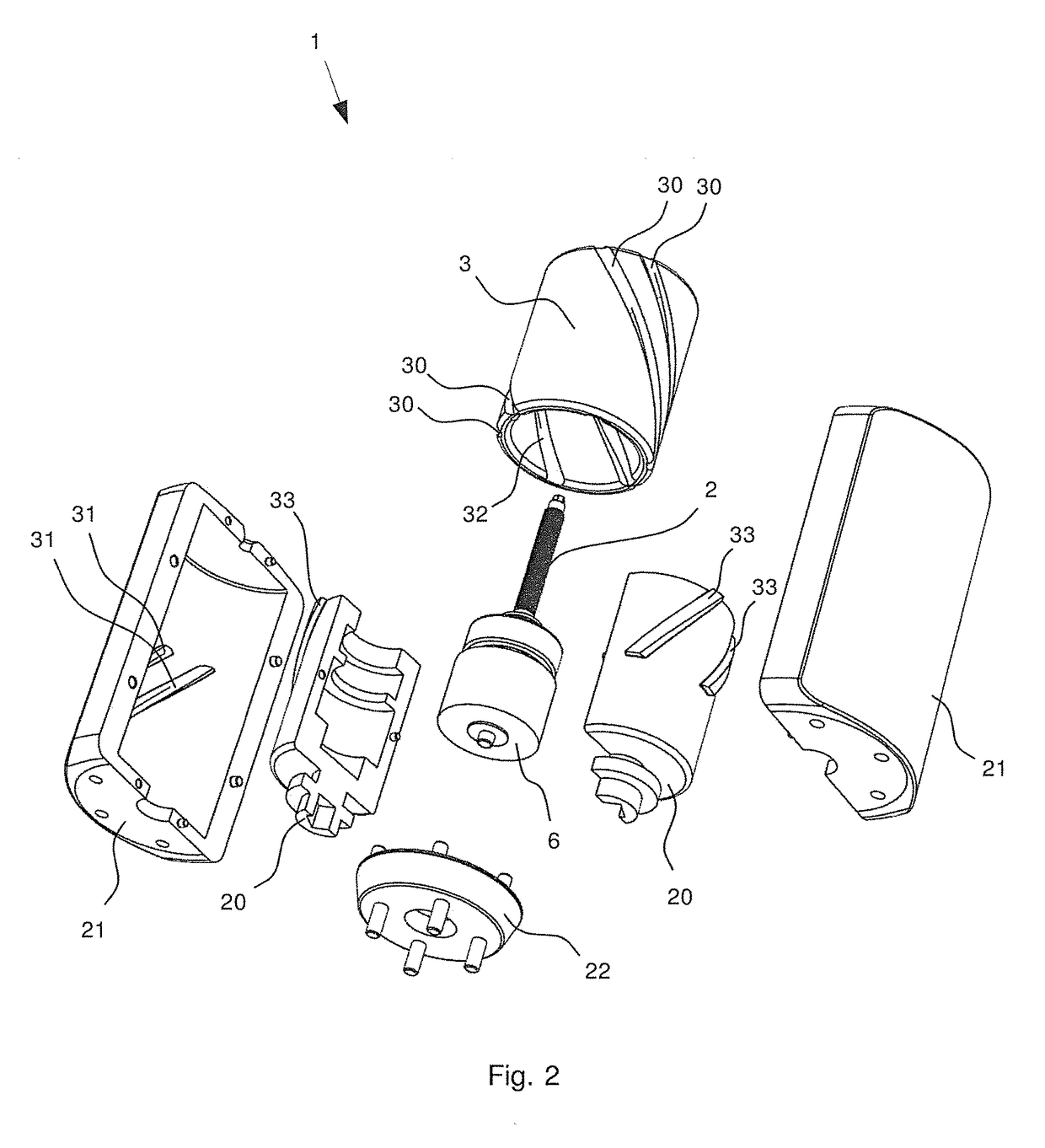
[0122]FIG. 1 shows an exploded representation of an actuation device 1 in a perspective view from above. The actuation device 1 includes a drive shaft 2, an intermediate body 3 and a reference body 4, which is composed of two equal housing halves 21 as well as a base plate 22. The actuation device 1 moreover includes a driven body 5, which is composed of two equal driven body halves 20, and a drive 6. The drive 6 in this case is an electrical stepper motor.

[0123]The intermediate body 3, the reference body 4 and the driven body 5 are manufactured from plastic. The driven body halves 20 are designed equally, and the housing halves 21 are likewise designed equally, which permits a simple and inexpensive manufacture. The assembly, maintenance and repair of the actuation device 1 is moreover simple, rapid and inexpensive, due to the fact that the driven body 5 and the reference body 4 can be put ...


PUM


Abstract

Control equipment for generating a rotational travel motion from a rotational drive motion includes a drive shaft, an intermediate body, a reference body, and an output body that are movable relative to each other. The control equipment includes a first transmission and a second transmission, which is different from the first transmission. The first transmission transforms a rotational movement of the drive shaft relative to the reference body into a linear motion component of the intermediate body relative to the reference body, and the control equipment has a displacement line along which the intermediate body moves via the linear motion component of the intermediate body relative to the reference body. The second transmission transforms the linear motion component of the intermediate body relative into a rotational movement of the output body relative to the reference body.

Description

BACKGROUND OF THE INVENTION[0001]Field of the Invention[0002]The invention relates to the field of actuation devices for producing a rotational actuation movement from a rotational drive movement. In particular, the invention relates to the field of actuation devices for the rotational adjustment of a valve. A further aspect of the invention relates to the field of devices which include have a fail-safe mechanism and an actuation device.[0003]Description of Related Art[0004]A rotational actuation movement is typically a movement of a few revolutions or a fraction of a revolution. A rotational actuation movement therefore includes a pivoting movement (for example by 90 degrees or by 60 degrees) as well as a rotating movement.[0005]In the current state of the art, an actuation device for rotational movements by a rotational drive movement is typically driven by way of the rotational drive movement being transmitted onto a drive output via gearwheel transmissions, chains and / or belts, ...

Claims


Application Information

Patent Timeline
Patent Type & Authority Applications(United States)
IPC IPC(8): F16H25/20H02K37/24F16K31/04
CPCF16H25/205H02K37/24F16K31/043F16H25/20F16K31/047H02K7/06H02K7/14F16K31/041
Inventor STOLL, KURTRIEK, ALFONSSIGRIST, MARTINMOCK, ELMARMALZACH, SAMUEL
Owner FESTO AG & CO KG
Learn More