
Motor having rotor of optimized shape

a technology of optimizing shape and rotor, which is applied in the direction of dynamo-electric machines, magnetic circuit rotating parts, and shape/form/construction of magnetic circuits, etc. it can solve the problems of increasing the number of components and man-hours, reducing the output of motors, and not completely eliminating fundamental components. , to achieve the effect of reducing the cogging torqu

Active Publication Date: 2017-05-18
FANUC LTD
View PDF4 Cites 0 Cited by
  • Summary
  • Abstract
  • Description
  • Claims
  • Application Information

AI Technical Summary

Benefits of technology

The invention aims to create a motor with a rotor that has a shape that eliminates cogging torque, which is caused by the number of poles in the rotor and slots in the stator. This results in a significant reduction of cogging torque.

Problems solved by technology

Conventional shape optimization aims at reducing a fundamental component, but cannot completely eliminate the fundamental component.
However, the skew structure may cause a reduction in the output of motors.
Also, the skew structure increases the number of components and man-hours, thus increasing costs.

Method used


Image

  • Motor having rotor of optimized shape
  • Motor having rotor of optimized shape
  • Motor having rotor of optimized shape

Examples


Embodiment Construction

[0039]A motor according to the present invention will be described below with reference to the drawings. FIG. 4 is a sectional view of the motor according to an embodiment of the present invention. A motor 100 according to the embodiment of the present invention has a rotor 1 and a stator 2. The rotor 1 has a rotor core 11 and a plurality of magnetic poles 13 including permanent magnets 12 provided in the rotor core 11. The stator 2 has a stator core 23 in which a plurality of teeth 21 and slots 22 are formed. The plurality of teeth 21 are disposed on the side of the outer periphery of the rotor 1 so as to be opposed to the plurality of magnetic poles 13. The slots 22 contain armature winding (not shown) wound around the plurality of teeth 21.

[0040]In the motor 100 according to the embodiment of the present invention, the rotor 1 is structured such that the distance r(θ) between the center C of the rotor 1 and the outer periphery of the rotor 1 satisfies the following equations (1) ...


PUM


Abstract

A motor according to an embodiment of the present invention includes a rotor having a rotor core and a plurality of magnetic poles including permanent magnets provided in the rotor core; and a stator having a stator core in which a plurality of teeth disposed on the side of the outer periphery of the rotor so as to be opposed to the plurality of magnetic poles and slots for containing armature winding wound around the plurality of teeth are formed. The rotor is structured such that the distance r(θ) between the center of the rotor and the outer periphery thereof satisfies the following equations (1) and (2):∫-φφf(θ)2-r(θ)2θ≤φ(R2-r02)10(1)∫-φφr1(θ)2-r(θ)2θ>0(2)

Description

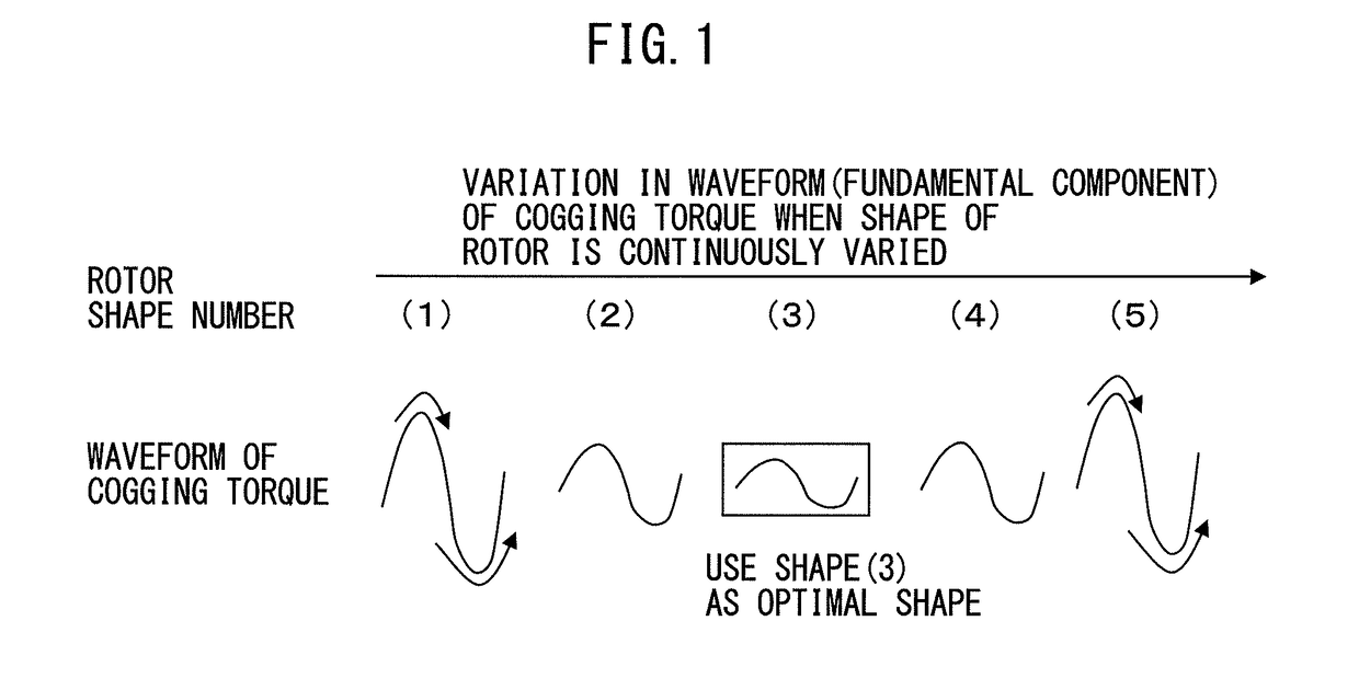
BACKGROUND OF THE INVENTION[0001]1. Field of the Invention[0002]The present invention relates to a motor, and specifically relates to a motor having a rotor of optimized shape.[0003]2. Description of Related Art[0004]It is generally known that the fundamental frequency component (hereinafter referred to as “fundamental component”) of a cogging torque per rotation of a rotor, which can be reduced by optimizing the shape of the rotor, appears at a frequency of the least common multiple of the number of poles of the rotor and the number of teeth of a stator.[0005]To reduce the fundamental component of a cogging torque, rotors have been conventionally optimized in shape in various ways. FIG. 1 shows a variation in the waveform (fundamental component) of a cogging torque, when a rotor is continuously varied in shape. Assuming that, when the rotor is gradually varied in shape from (1) to (5), the cogging torque has the lowest amplitude in the shape of (3). In this case, the shape of (3) i...

Claims


Application Information

Patent Timeline
Patent Type & Authority Applications(United States)
IPC IPC(8): H02K1/27H02K3/18H02K21/16H02K1/14
CPCH02K1/274H02K1/146H02K2213/03H02K21/16H02K3/18
Inventor ARAI, LEO
Owner FANUC LTD
Learn More