
Permanent magnet rotary motor

a permanent magnet, rotary motor technology, applied in the direction of magnetic circuit rotating parts, magnetic circuit shape/form/construction, association with control/drive circuits, etc., can solve the problems of motor vibration and speed variation, torque reduction, torque ripple, etc., to reduce cogging torque and torque ripple

Inactive Publication Date: 2007-10-02
SANYO DENKI CO LTD
View PDF24 Cites 4 Cited by
  • Summary
  • Abstract
  • Description
  • Claims
  • Application Information

AI Technical Summary

Benefits of technology

The present invention provides a permanent magnet rotary motor that reduces cogging torque and torque ripple. This is achieved by improving the arrangement of the stator and rotor, which reduces the impact of magnetic flux concentration on the stator magnetic pole sections. The motor includes a rotor with a rotor core and P rotor magnetic pole sections, and a stator with N stator magnetic pole sections. The motor also includes N slots in the stator, with each slot having an opening portion. The currents flowing through the winding sections have a phase difference of 120°, which further reduces torque ripple. The divided cores in the stator core are shaped to have equal open angle, which reduces cogging torque. The motor is easy to manufacture and has a uniform torque distribution.

Problems solved by technology

Such cogging torque hinders smooth rotation of the motor, thus causing vibration and speed variation of the motor.
However, formation of the skew may reduce the torque or reduce the productivity of the motor.
Further, use of the permanent magnet of the eccentric type cannot increase the magnetic flux density of the motor, so that higher torque density cannot be achieved.
Thus, in order to manufacture the stator core, the number of component types must be increased, and manufacture of the assembly of the stator core thus may become complicated.
However, the torque is reduced, so that torque ripple is increased.

Method used


Image

  • Permanent magnet rotary motor
  • Permanent magnet rotary motor
  • Permanent magnet rotary motor

Examples


first embodiment

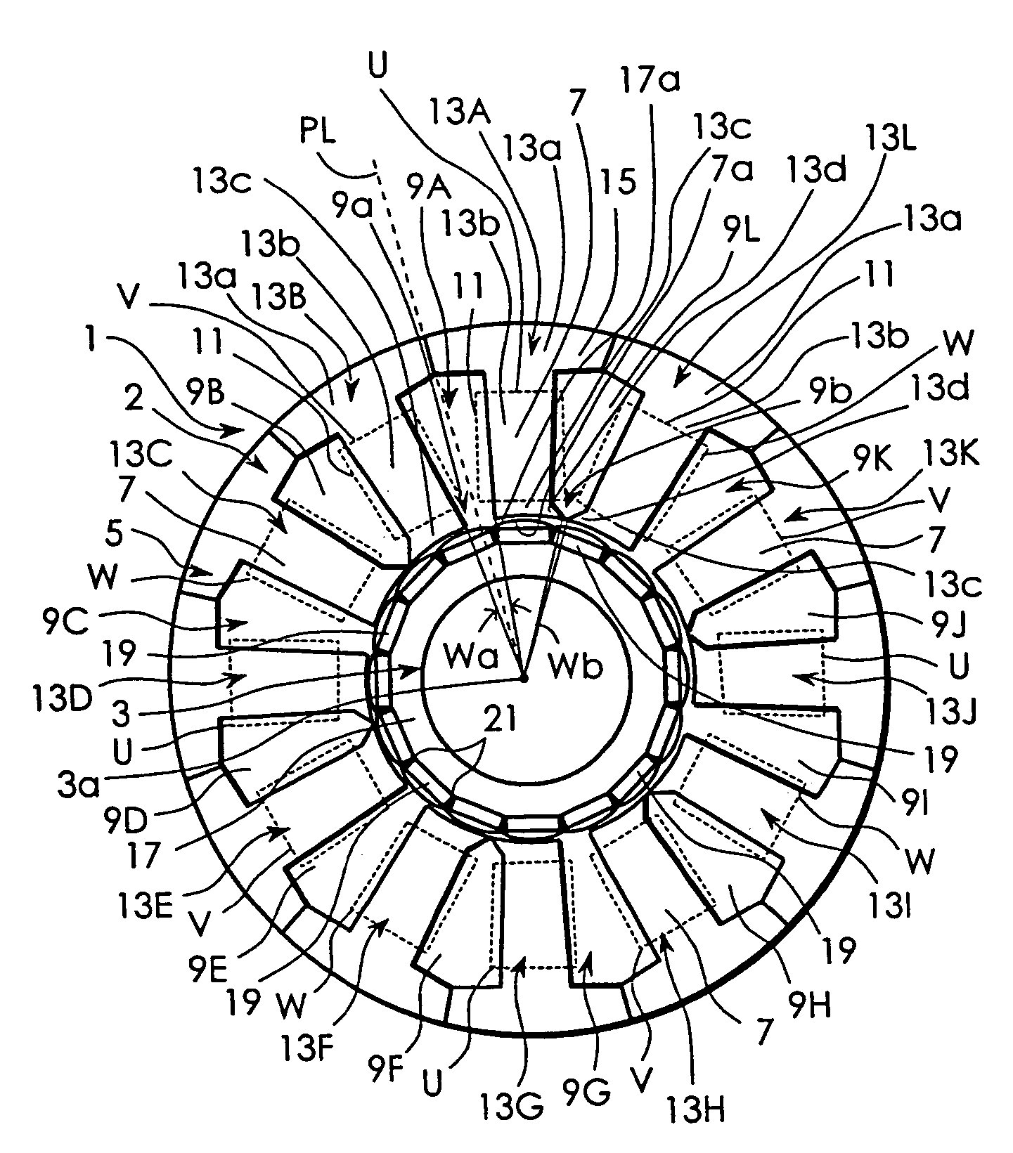
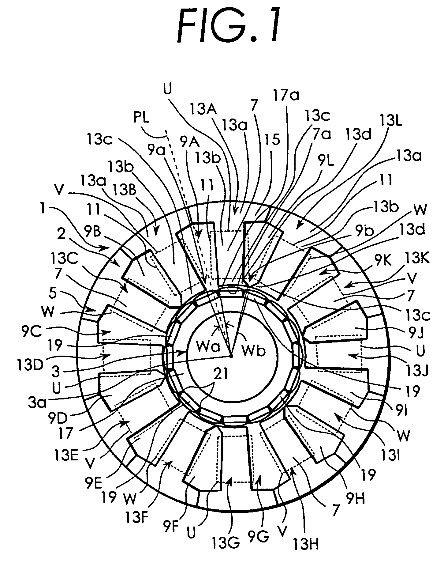
[0036]Embodiments of the present invention will be described below in detail with reference to the appended drawings. FIG. 1 is a schematic diagram showing a stator 1 and a rotor 3 of a permanent magnetic rotary motor used for explaining the present invention. As shown in FIG. 1, the stator 1 has a stator core 2 and winding sections 11. The stator core 2 has a cylindrical yoke 5 and 12 stator magnetic pole sections 7 that extend from the inner periphery of the yoke 5 toward the center of the stator core. Each of the 12 stator magnetic pole sections 7 has a magnetic surface 7a at a leading end thereof.

[0037]The stator core 2 is constituted by 12 divided cores 13A to 13L arranged in combination in a peripheral direction of the rotor 3. The arrangement is such that the 12 divided cores 13A to 13L are alternately inverted or turned over in the peripheral direction. The divided cores 13A to 13L are configured by laminating a plurality of steel plates 15 in an axis line direction of the r...

second embodiment

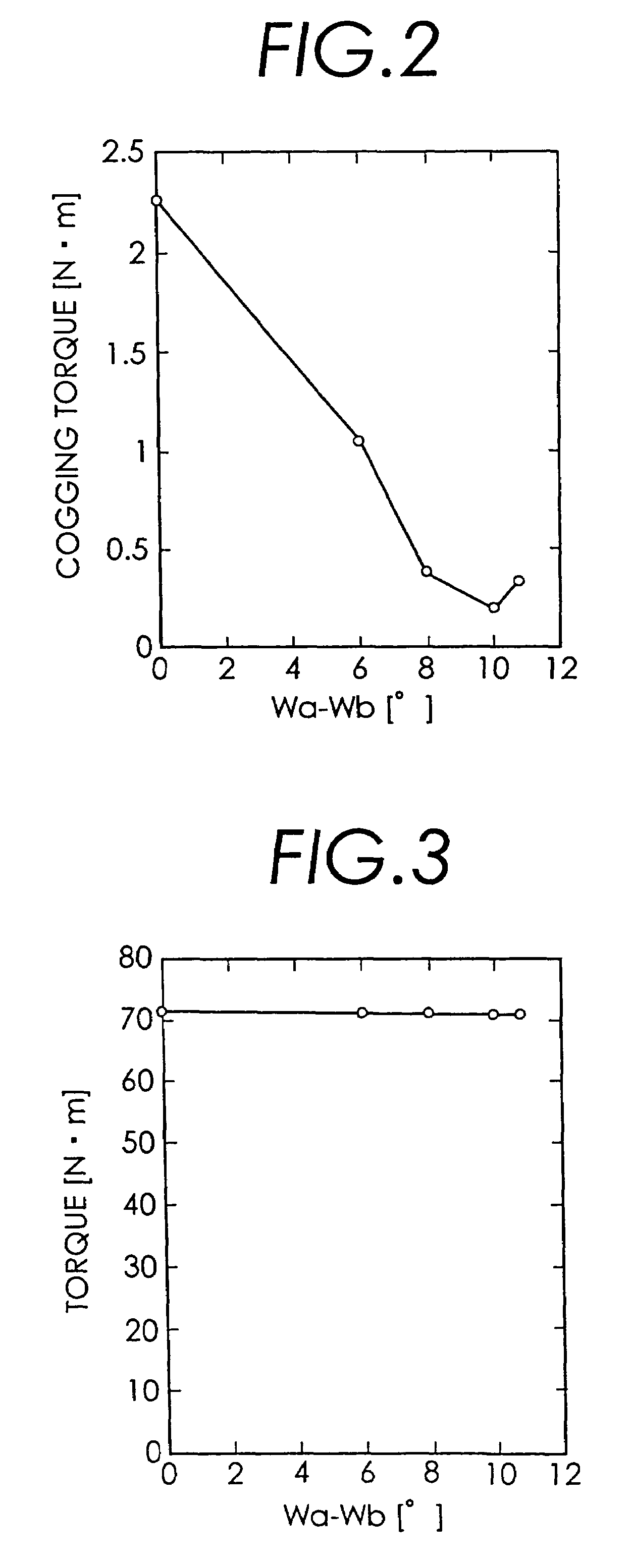
[0050]In the second embodiment, FIG. 7 is a graph indicating results obtained by examining the relationship between a rotor rotation angle and the cogging torque when the angle difference Wa−Wb is set to 0° and the relationship between the rotor rotation angle and the cogging torque when the angle difference Wa−Wb is set to 5°. It can be seen from FIG. 7 that when the angle difference Wa−Wb is set to 5°, the amount of the cogging torque produced at the time of a change of the rotor rotation angle can be reduced more than when the angle difference Wa−Wb is set to 0°.

[0051]Next, in a permanent magnet rotary motor in which the least common multiple LCM (P, N) of the P and the N becomes equal to the least common multiple LCM of the ½ P and the N, the relationship between the value of the angle difference Wa−Wb and the cogging torque was examined. More specifically, tests were carried out using the permanent magnet rotary motor having 10 poles and 12 slots. In the permanent magnet rotary...


PUM


Abstract

There is provided a permanent magnet rotary motor in which manufacture of a stator core is facilitated. The permanent magnet rotary motor includes P rotor magnetic pole sections and N slots. In this permanent magnet rotary motor, a least common multiple LCM (P, N) is set to be different from a least common multiple LCM (P / 2, N), and an exciting winding is wound on each of N stator magnetic pole sections arranged in a peripheral direction so that a 120° current phase difference is obtained. N / 2 divided cores 13A, 13C, 13E, 13G, 13I, and 13K of a first divided core group and N / 2 divided cores 13B, 13D, 13F, 13H, 13J, and 13L of a second divided core group constitute a stator core 2. Cross-sectional shapes of the divided cores in the first and second divided core groups arranged on both sides of each of slots 9A to 9L taken in a direction perpendicular to an axis line passing through the center of a rotor 3 are shaped to be axisymmetrical with respect to a virtual line PL passing through the middle of an opening portion 9a or 9b of each slot and the axis line of the rotor 3. An open angle Wa of an opening portion 9a is set to be smaller than an open angle Wb of an opening portion 9b.

Description

BACKGROUND OF THE INVENTION[0001]The present invention relates to a permanent magnet rotary motor in which a rotor including rotor magnetic pole sections formed of permanent magnets rotates.[0002]Permanent magnet rotary motors have the rotor and a stator. Some rotors have a rotor core and the rotor magnetic pole sections formed of the permanent magnets. Some stators have a stator core including a plurality of stator magnetic pole sections, a plurality of slots having openings that open toward the rotor core, and exciting windings of at least two phases wound on these stator magnetic pole sections. It is known that, in the motor that uses the permanent magnets for the rotor magnetic pole sections, pulsating torque (cogging torque) and a thrust force are produced at the time of no-load operation. Such cogging torque hinders smooth rotation of the motor, thus causing vibration and speed variation of the motor. As an approach to reducing the cogging torque, there have been hitherto prop...

Claims


Application Information

Patent Timeline
Patent Type & Authority Patents(United States)
IPC IPC(8): H02K1/17H02K1/14H02K1/18H02K1/27H02K21/12H02K1/16H02K21/16
CPCH02K21/16H02K3/28H02K1/276H02K2213/03H02K21/14H02K1/16H02K3/12H02K2213/12H02K11/33
Inventor MIYASHITA, TOSHIHITOKOICHI, SHINTARO
Owner SANYO DENKI CO LTD
Learn More