
Rotor and motor using same

Inactive Publication Date: 2019-12-05
NIDEC CORP
View PDF1 Cites 0 Cited by
  • Summary
  • Abstract
  • Description
  • Claims
  • Application Information

AI Technical Summary

Benefits of technology

The patent aims to reduce issues like cogging torque and torque ripple in motors by controlling the flow of magnetic flux in the rotor core, which results in magnetic imbalance. The technical effect of this patent is to improve the performance of motors and reduce their energy consumption.

Problems solved by technology

In general, in the consequent-pole motor using a part of the rotor core as a pseudo pole, imbalance of magnetic characteristics between respective magnetic poles is large, as compared to a general motor in which all magnetic poles are rotor magnets.
That is, in the rotor of the consequent-pole motor, since the part of the rotor core is used as a magnetic pole, magnetic imbalance occurs between a magnetic pole configured with the rotor magnet and a magnetic pole configured with the part of the rotor core.
In this way, when magnetic imbalance occurs in the rotor, cogging torque and torque ripple are generated in the motor.
That is, since a direction and the amount of the magnetic flux flowing through the salient pole portions of the rotor core depend on the shapes of the salient pole portions, the rotor is magnetically unbalanced.
In the conventional structure, when the slit formed inside the rotor core is not opened in the outer surface of the salient pole (the salient pole portion) of the rotor core, that is, when the outer surface of the salient pole portion of the rotor core is connected in the circumferential direction, flow of the magnetic flux is disturbed at the connected portion, and thus it is difficult to control the magnetic flux as designed.

Method used


Image

  • Rotor and motor using same
  • Rotor and motor using same
  • Rotor and motor using same

Examples


Embodiment Construction

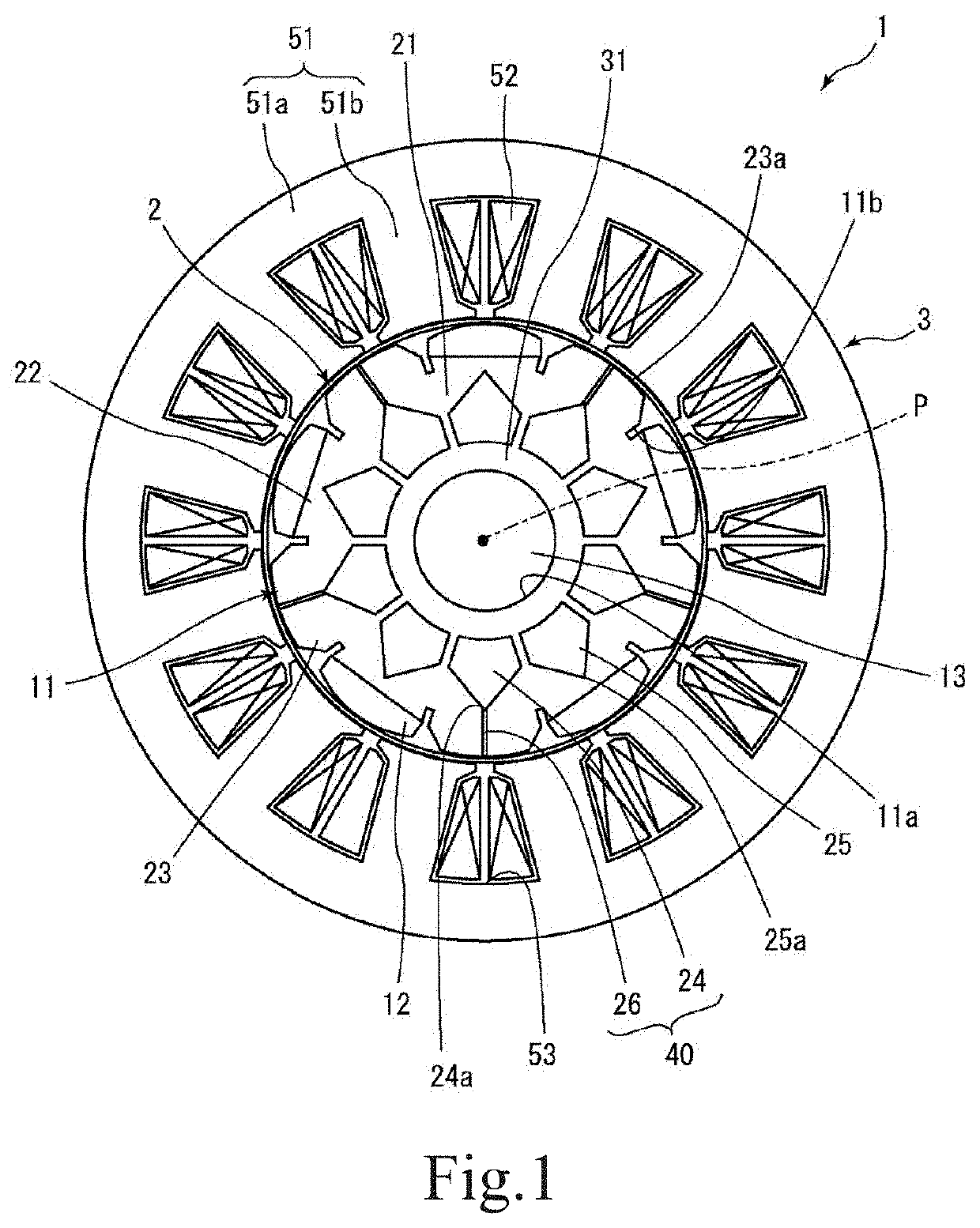
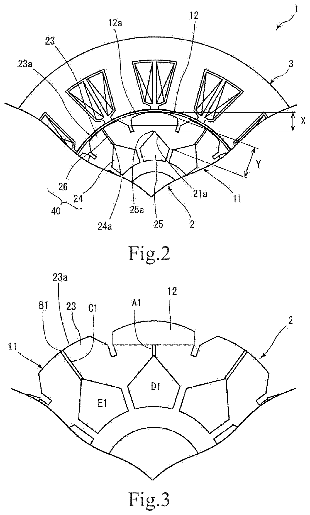
[0023]Hereinafter, example embodiments of the present disclosure will be described in detail with reference to the drawings. The same or corresponding components in the drawings are denoted by the same reference numerals, and description thereof will not be repeated. Further, the dimensions of constituent members in each drawing do not reliably represent the actual dimensions of the constituent members and the dimensional ratios of the constituent members.

[0024]In the following description, a direction that is parallel to a central axis of a rotor is referred to as an “axial direction”, a direction that is perpendicular to the central axis of the rotor is referred to as a “radial direction”, and a direction along a circular arc with the central axis as a center is referred to as a “circumferential direction”. However, the definition of the directions is not intended to limit directions of the rotor and a motor according to the present disclosure at a time of use.

(Entire Configuratio...


PUM


Abstract

A rotor includes a cylindrical rotor core including salient pole portions protruding in a radial direction and extending along a central axis, and rotor magnets alternately arranged with the salient pole portions in a circumferential direction on an outer circumferential surface of the rotor core. The rotor core includes a cylindrical core portion, a first space penetrating the core portion in an axial direction and located radially inward of the core portion with respect to the salient pole portions, a second space penetrating the core portion in the axial direction and located radially inward of the core portion with respect to the rotor magnets, and a slit extending from the first space to an outer circumferential surface of the salient pole portion and being open to the outer surface.

Description

CROSS REFERENCE TO RELATED APPLICATIONS[0001]This is the U.S. national stage of application No. PCT / JP2018 / 000570, filed on Jan. 12, 2018, and priority under 35 U.S.C. § 119(a) and 35 U.S.C. § 365(b) is claimed from Japanese Application No. 2017-008443, filed Jan. 20, 2017; the contents of which are incorporated herein by reference.1. FIELD OF THE INVENTION[0002]The present disclosure relates to a rotor and a motor using the same.2. DESCRIPTION OF THE RELATED ART[0003]In the related art, a configuration including a rotor core and a rotor magnet has been known as a rotor used for a motor. In recent years, a configuration of the rotor in which the amount of use of the rotor magnet is reduced because of a rise in the price of the rotor magnet due to a rise in a price of the rare earth has been studied. Conventionally, a consequent-pole motor using a part of the rotor core as a pseudo pole has been known as a motor in which the amount of use of the rotor magnet of the rotor is reduced.[...

Claims


Application Information

Patent Timeline
IPC IPC(8): H02K1/24H02K1/27H02K1/26
CPCH02K1/24H02K1/26H02K1/27H02K1/2781H02K1/2746
Inventor UEDA, TOMOYA
Owner NIDEC CORP
Learn More