
Electric motor

a technology of electric motors and motors, applied in the direction of mechanical energy handling, dynamo-electric components, synchronous machines with stationary armatures, etc., can solve the problems of increasing abrupt change of magnetic flux gap generation between rotor core materials, etc., to reduce cogging torque and torque ripple

Active Publication Date: 2012-03-13
PANASONIC CORP
View PDF13 Cites 5 Cited by
  • Summary
  • Abstract
  • Description
  • Claims
  • Application Information

AI Technical Summary

Benefits of technology

"The present invention is an electric motor with a stator and a rotor. The stator has slots and winding, while the rotor has magnetic poles. The rotor core is formed by equally dividing materials into predetermined sections. The configuration reduces cogging torque and torque ripple while using a rotor core formed by multiple sections. The technical effect is to improve the performance of the electric motor."

Problems solved by technology

However, when a rotor core formed by rotor core materials as mentioned in Patent document 1 is used, gaps are generated between rotor core materials.
As a result, abrupt change of the magnetic flux is generated between the rotor core material and the gap.
This gives rise to the problem of increase of cogging torque and torque ripple.

Method used


Image

  • Electric motor
  • Electric motor
  • Electric motor

Examples


embodiment 1

Preferred Embodiment 1

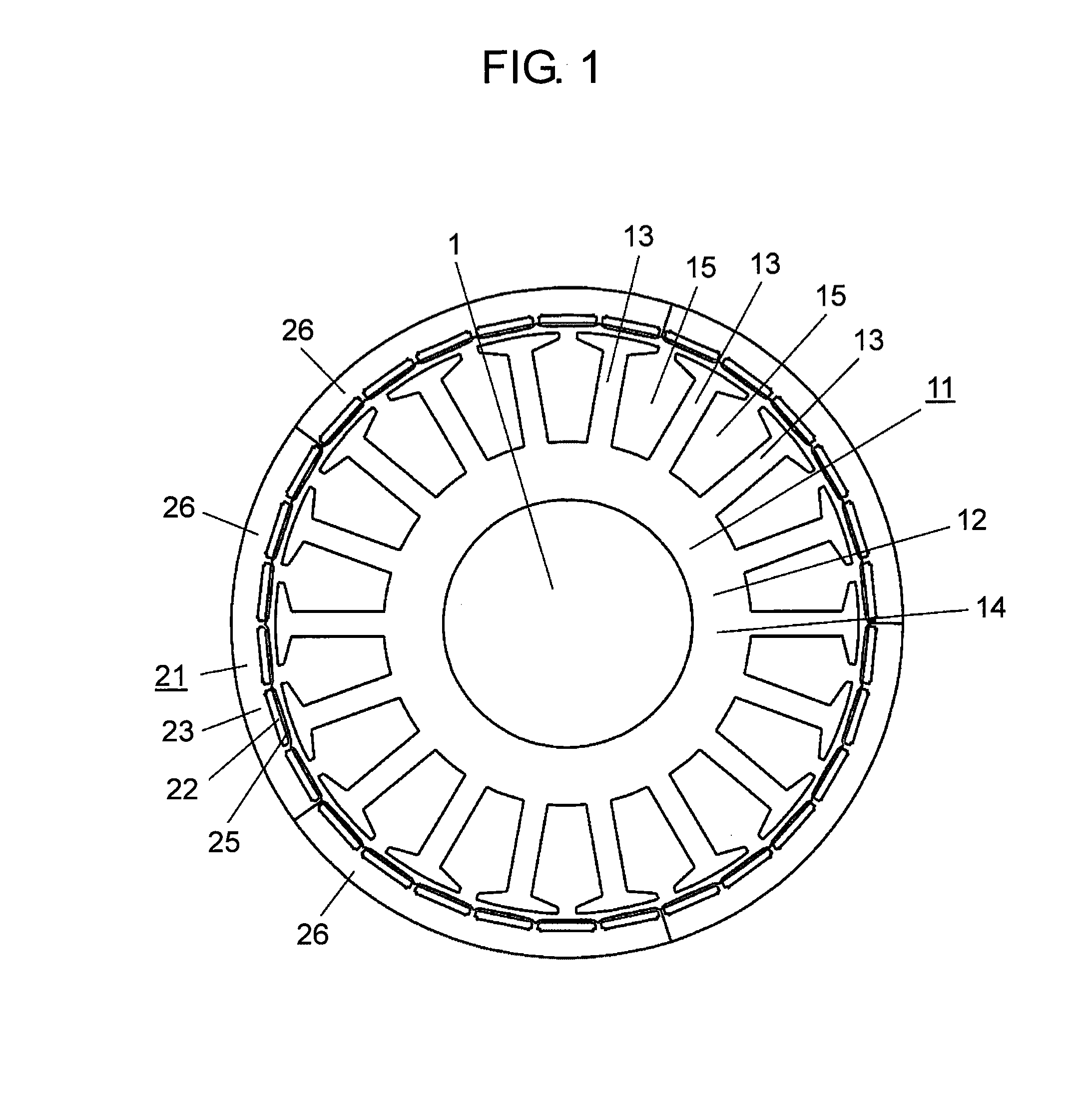
[0052]FIG. 1 is a sectional view of an electric motor in the preferred embodiment 1 of the present invention.

[0053]The electric motor in the preferred embodiment 1 comprises stator 11 and rotor 21.

[0054]Stator 11 includes stator core 14 formed for example by punching by a press and laminating a plurality of thin steel sheets having high magnetic permeability, and winding (not shown) wound around stator core 14. Stator core 14 has nearly annular yoke 12 and a plurality of teeth 13 protruding outward from yoke 12, and slot 15 is formed between teeth 13 adjacent to each other. The winding is wound around stator core 14 in a concentrated fashion and housed in slot 15.

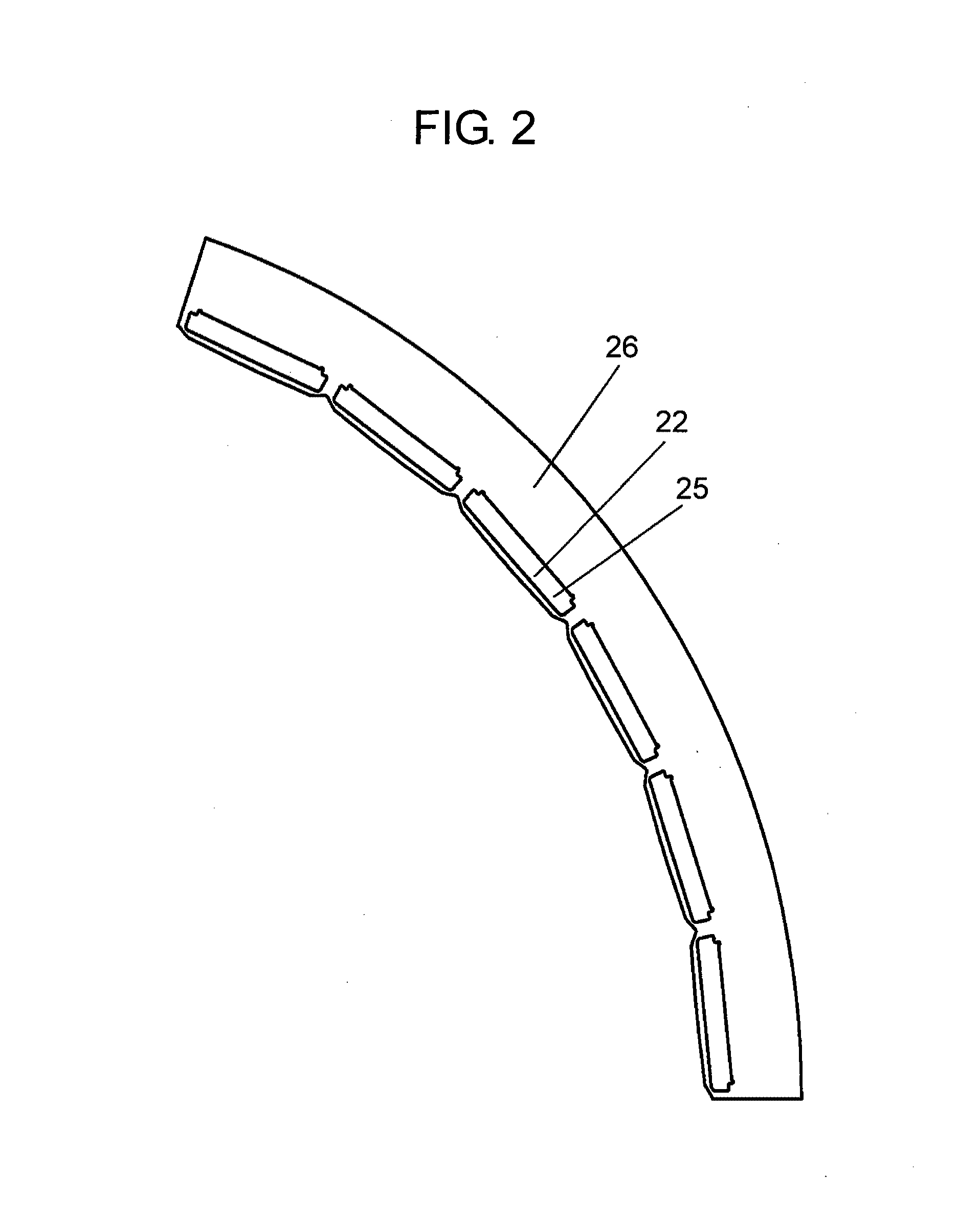
[0055]Rotor 21 includes rotor core 23 formed with a plurality of magnet burying holes 22, and permanent magnets 25 to be buried in respective magnet burying holes 22. Permanent magnets 25 are disposed for forming magnetic poles at rotor 21, and such permanent magnets 25 are kept and housed in respectiv...

embodiment 2

Preferred Embodiment 2

[0081]The preferred embodiment 2 of the present invention will be described in the following with reference to the drawings.

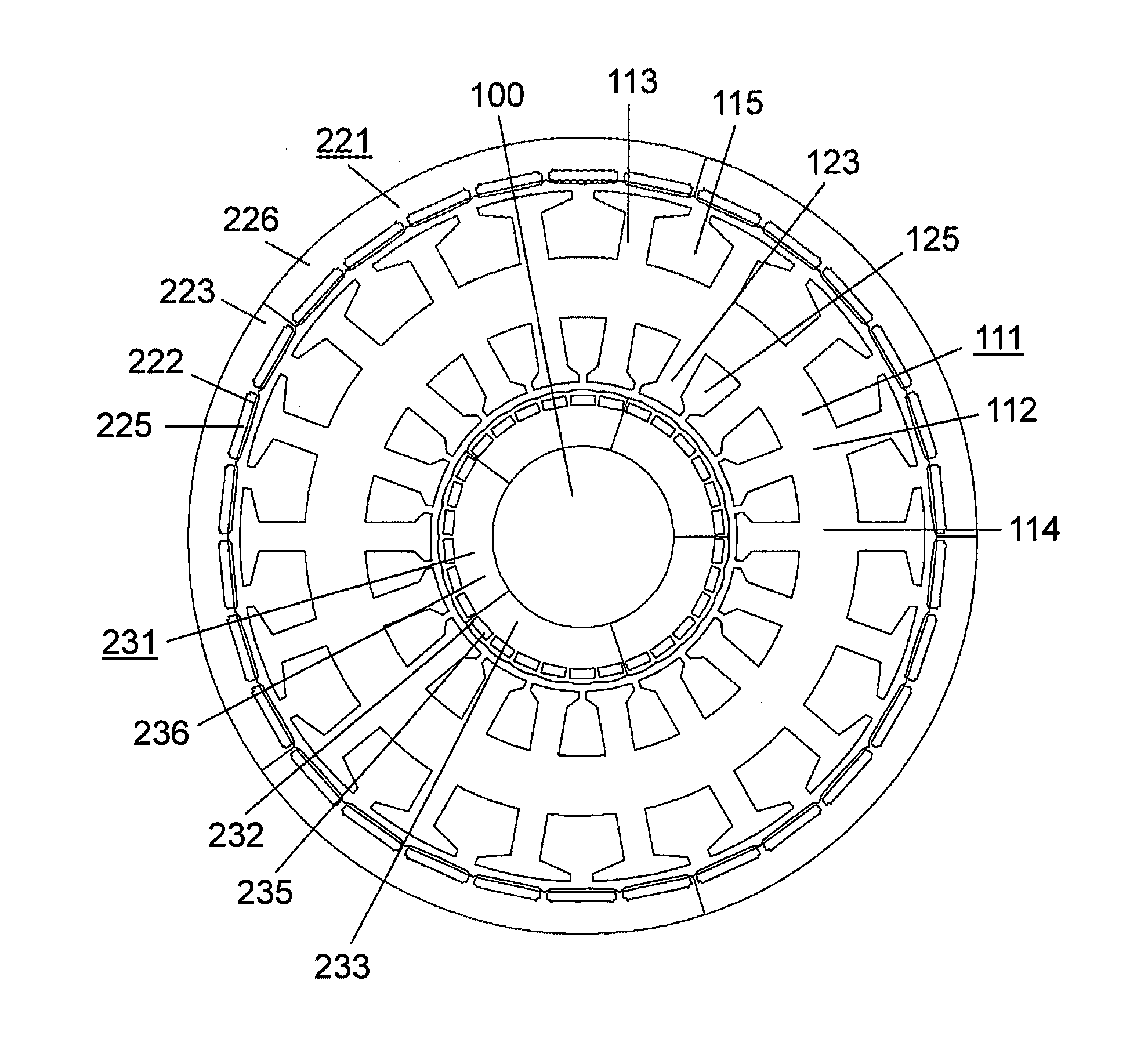
[0082]FIG. 10 is a sectional view of an electric motor in the preferred embodiment 2 of the present invention.

[0083]The electric motor in the preferred embodiment 2 comprises stator 111, outer rotor 221, and inner rotor 231.

[0084]Stator 111 includes stator core 114 formed for example by punching by a press and laminating a plurality of thin steel sheets having high magnetic permeability, and winding (not shown) wound around stator core 114. Stator core 114 has nearly annular yoke 112, a plurality of outer teeth 113 protruding outward from yoke 112, and a plurality of inner teeth 123 protruded inward from yoke 112. Also, stator core 114 is formed with outer slot 115 between outer teeth 113 adjacent to each other, and with inner slot 125 between inner teeth 123 adjacent to each other. As to the winding system for winding around stator core 1...


PUM


Abstract

It comprises stator including stator core having yoke and a plurality of teeth protruded from yoke, which is formed with slots between adjacent teeth, and rotor having rotor core and permanent magnet formed with a plurality of magnetic poles, which confronts tip ends of teeth via gaps, wherein rotor core is formed by rotor core materials circumferentially equally divided into the predetermined number of divisions, and the least common multiple being N for the number of slots and the number of magnetic poles and the least common multiple being M for the number of slots and the number of divisions, then N is equal to M.

Description

[0001]This Application is a U.S. National Phase Application of PCT International Application PCT / JP2008 / 000857.TECHNICAL FIELD[0002]The present invention relates to an electric motor using a rotor core formed by a plurality of circumferentially divided rotor core materials.BACKGROUND ART[0003]As to a rotor core formed by a plurality of circumferentially divided rotor core materials, technology as mentioned in Patent document 1 is commonly known. The technology mentioned in Patent document 1 is such that these rotor core materials are connected to each other with some play provided via junctions in such manner as to be positioned in an annular fashion. And, in this condition, they are set in a mold and integrated into one piece by a steel frame and resin in the mold.[0004]Due to the technology mentioned in Patent document 1, when rotor core materials are set in a mold, rotor core materials are connected to each other with some play provided via junctions, and therefore, the rotor cor...

Claims


Application Information

Patent Timeline
Patent Type & Authority Patents(United States)
IPC IPC(8): H02K21/12
CPCH02K21/16H02K21/222H02K29/03H02K1/278H02K1/2786H02K1/2791
Inventor LI, HUYOSHIKAWA, YUICHIMURAKAMI, HIROSHI
Owner PANASONIC CORP
Learn More