
Rotor structure and rotor assembly of surface-mounted permanent magnet synchronous motor

A technology of permanent magnet synchronous motor and rotor structure, which is applied in the direction of electric components, magnetic circuit rotating parts, magnetic circuit shape/style/structure, etc. It can solve the problems of large torque fluctuation, easy vibration and noise, and high cost. Achieve the effect of reducing harmonic distortion rate, reducing weight and cost, reducing cogging torque and torque ripple

Pending Publication Date: 2019-11-12
浙江新能机电科技有限公司
View PDF0 Cites 3 Cited by
  • Summary
  • Abstract
  • Description
  • Claims
  • Application Information

AI Technical Summary

Problems solved by technology

[0004] There are mainly two types of rotor structures for existing surface-mounted permanent magnet synchronous motors: one type of magnetic steel has both inner and outer surfaces as arcs, and the radius of the arc on the inner surface is greater than the radius of the arc on the outer surface to form a middle thick double The cross-sectional shape of the end gradually becomes thinner. Although this structure can effectively reduce the torque fluctuation and positioning torque, thereby reducing the vibration noise, but this structure causes a large waste of magnetic steel materials and high cost; another surface-mounted magnetic steel, The center of the inner arc and the outer arc of the magnetic steel are at the same point, and coincide with the center of the shaft hole. The radius of the outer arc is greater than the radius of the inner arc, and the thickness of the magnetic steel is equal. This structure has large torque fluctuations and is prone to vibration noise

Method used


Image

  • Rotor structure and rotor assembly of surface-mounted permanent magnet synchronous motor
  • Rotor structure and rotor assembly of surface-mounted permanent magnet synchronous motor
  • Rotor structure and rotor assembly of surface-mounted permanent magnet synchronous motor

Examples


Embodiment approach

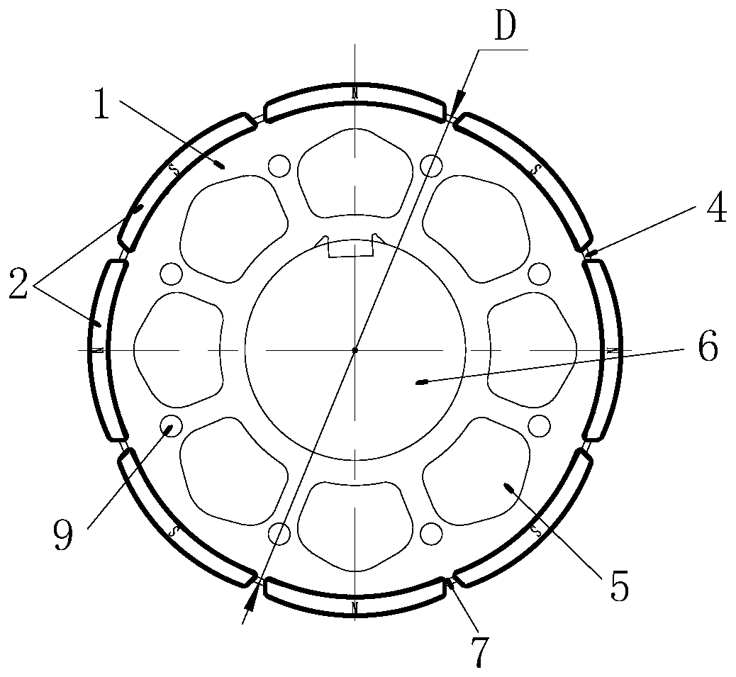
[0044] As the first embodiment of the magnetic steel bit and the magnetic steel, such as Figure 5As shown, the magnetic steel position 3 is a parallel groove, and the groove edges 31 on both sides of the magnetic steel position 3 are parallel to each other, as Image 6 As shown, the magnetic steel 2 is a parallel magnetic steel, and the two side lines 21 of the magnetic steel 2 are parallel to each other.

[0045] As the second embodiment of the magnetic steel bit and the magnetic steel, such as Figure 7 As shown, the magnetic steel position 3 is a dovetail groove, and the straight lines where the groove edges 32 on both sides of the magnetic steel position 3 intersect each other, and the angle formed is γ, as Figure 8 As shown, the magnetic steel 2 is a dovetail type magnetic steel, the straight lines where the side lines 22 on both sides of the magnetic steel 2 intersect each other, and the angle formed is γ1, γ=γ1, and the angle between γ and γ1 can be set according to ...


PUM


Abstract

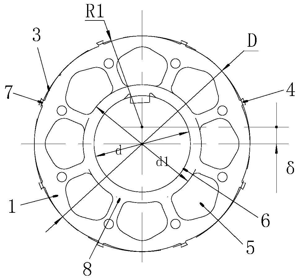
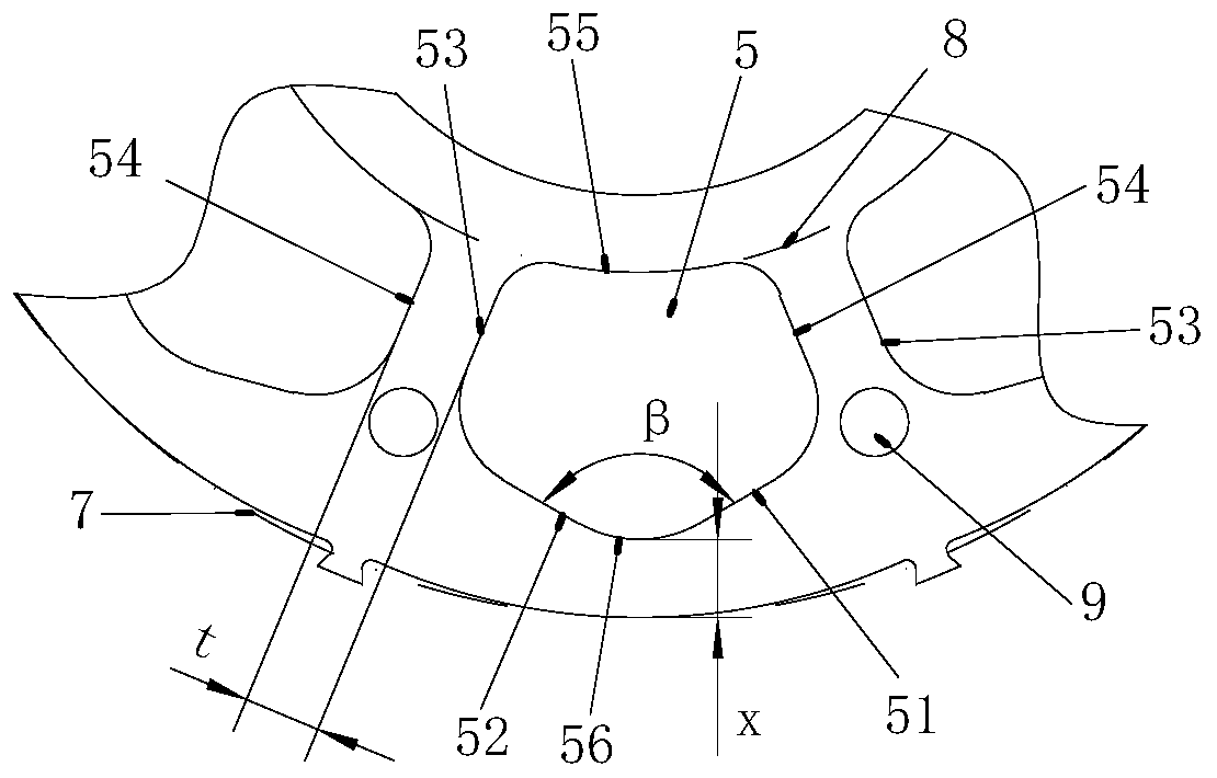
The invention belongs to the technical field of surface-mounted permanent magnet synchronous motors, in particular to a rotor structure and a rotor assembly of a surface-mounted permanent magnet synchronous motor. The rotor structure comprises a rotor punching sheet and a magnetic steel arranged on the rotor punching sheet; a plurality of magnetic steels are uniformly distributed on the circumferential surface of the rotor punching sheet, and a shaft hole is formed in the middle of the rotor punching sheet; the bottom of each magnetic steel is a cambered surface, and the circle center of eachcambered surface and the center of the shaft hole are eccentrically arranged. The rotor assembly comprises a plurality of rotor structures which are axially stacked and arranged. According to the rotor structure and the rotor assembly of the surface-mounted permanent magnet synchronous motor, the cogging torque of the motor can be effectively reduced, winding harmonic waves and tooth harmonic waves are reduced, the torque fluctuation of the motor is reduced to a great extent, the vibration noise of the motor is reduced, and the operation stability is improved.

Description

technical field [0001] The invention belongs to the technical field of a surface-mounted permanent magnet synchronous motor, in particular to a rotor structure and a rotor assembly of a surface-mounted permanent magnet synchronous motor. Background technique [0002] New energy vehicles are more and more popular with the public due to their environmental protection advantages. The auxiliary drive systems used in the internal vehicle air compressors and steering systems have more requirements for drive motors: high reliability, high performance, high Adaptability, while pursuing low cost, low weight, high response speed, etc. [0003] The surface-mounted permanent magnet synchronous motor (SPM) attaches the magnetic steel to the surface of the rotor core, and strengthens the magnetic steel by covering the surface of the magnetic steel with a stainless steel sleeve or winding carbon fiber (so that it will not be invalidated by centrifugal force), surface-mounted Permanent mag...

Claims


Application Information

Patent Timeline
IPC IPC(8): H02K1/27
CPCH02K1/278H02K2213/03
Inventor 朱锋霖晋兆海何婷婷
Owner 浙江新能机电科技有限公司
Learn More