Vector reduction model predictive control method for permanent magnet motor

A technology of model predictive control and permanent magnet motor, which is applied in motor control, vector control system, motor generator control, etc. It can solve the difficulties in heat dissipation design of high-power motor drive system, inverter commutation path and voltage vector confusion, It is difficult to predict the loss of switching devices and other issues, so as to achieve the effect of low torque ripple and high dynamic response, reasonable selection of voltage vector, and reduction of calculation load

Active Publication Date: 2021-11-26
SOUTHWEST JIAOTONG UNIV
View PDF8 Cites 5 Cited by
  • Summary
  • Abstract
  • Description
  • Claims
  • Application Information

AI Technical Summary

Problems solved by technology

However, there are two problems in the traditional MPC method used in ANPC inverters: one is the high computational complexity, which makes it difficult for the controller to adopt a higher sampling rate, and it is difficult to implement multi-step prediction; the other is the inverter's The commutation path and voltage vector are relatively chaotic, and it is difficult to predict the loss of switching devices, which brings difficulties to the heat dissipation design of high-power motor drive systems

Method used


Image

  • Vector reduction model predictive control method for permanent magnet motor
  • Vector reduction model predictive control method for permanent magnet motor
  • Vector reduction model predictive control method for permanent magnet motor

Examples


Embodiment Construction

[0067] The specific embodiments of the present invention are described below so that those skilled in the art can understand the present invention, but it should be clear that the present invention is not limited to the scope of the specific embodiments. For those of ordinary skill in the art, as long as various changes Within the spirit and scope of the present invention defined and determined by the appended claims, these changes are obvious, and all inventions and creations using the concept of the present invention are included in the protection list.

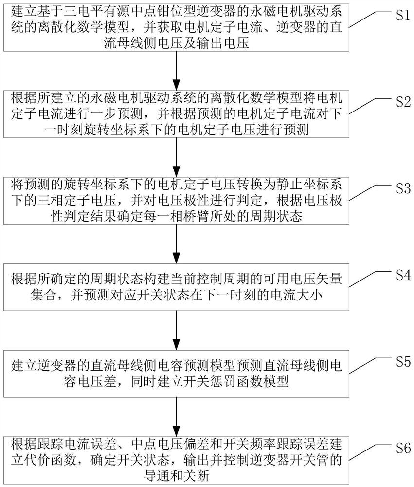
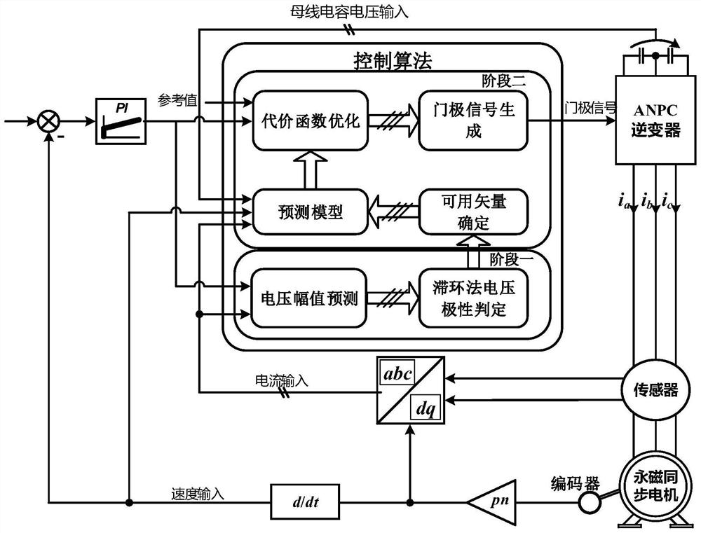
[0068] Such as figure 1 with figure 2 As shown, the embodiment of the present invention provides a method for predictive control of the reduced vector model of a permanent magnet motor, including the following steps S1 to S6:

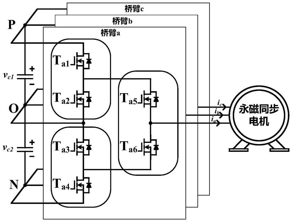
[0069] S1. Establish the discrete mathematical model of the permanent magnet motor drive system based on the three-level active neutral point clamped inverter, and obtain the stator current of the ...


PUM


Abstract

The invention discloses a vector reduction model prediction control method for a permanent magnet motor. The method comprises the following steps: establishing a discretization mathematical model of a permanent magnet motor driving system; predicting the stator voltage of the motor at the next moment; converting the motor stator voltage into a three-phase stator voltage in a static coordinate system, and judging the voltage polarity; constructing an available voltage vector set of the current control period, and predicting the current magnitude of the corresponding switching state at the next moment; establishing a direct current bus side capacitance prediction model of the inverter, and establishing a switch penalty function model at the same time; and establishing a cost function according to the tracking current error, the neutral-point voltage deviation and the switching frequency tracking error, determining a switching state, and outputting and controlling the on and off of an inverter switching tube. The three-level active neutral-point clamped inverter topology is decoupled into a high-frequency part and a low-frequency part, operation under different frequencies and different operation modes are achieved, and the complexity of a control algorithm and the loss of the inverter are effectively reduced.

Description

technical field [0001] The invention relates to the technical field of drive control of permanent magnet motors, in particular to a model predictive control method for reducing vector of permanent magnet motors. Background technique [0002] In recent years, permanent magnet synchronous motor (Permanent Magnet Synchronize Motor, PMSM) has received a lot of research and gradually applied to the high-power traction system of rail vehicles due to its advantages of high efficiency, high power density, large starting torque and strong overload capacity. Permanent magnet traction is considered to be one of the main development directions for the development of next-generation train traction technology, and has broad application prospects. As a device that directly drives the permanent magnet motor, the traction inverter's control performance and reliability are crucial to ensure the safe and efficient operation of the traction motor. [0003] Existing traction inverters mainly ad...

Claims


Application Information

Patent Timeline
Patent Type & Authority Applications(China)
IPC IPC(8): H02P21/14H02P21/22H02P25/022H02P27/06H02P27/12H02P6/10
CPCH02P21/14H02P21/22H02P25/022H02P27/06H02P27/12H02P6/10H02P2207/05
Inventor 马光同孙振耀徐帅姚春醒任冠州张晗
Owner SOUTHWEST JIAOTONG UNIV
Why Eureka
Try Eureka