Camera module and terminal device
- Summary
- Abstract
- Description
- Claims
- Application Information
AI Technical Summary
Benefits of technology
Problems solved by technology
Method used
Image

Examples
Example
Embodiment 1
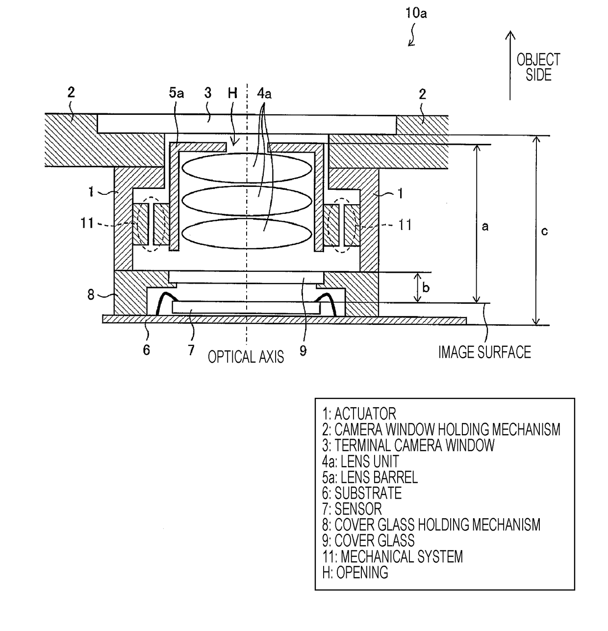
[0020]FIG. 1 is a sectional view illustrating a structure of a camera module 10a according to Embodiment 1 of the present invention. The camera module 10a is a camera module including a sensor (image sensor) 7 that converts optical signals received through a lens unit 4a into electrical signals. As illustrated in FIG. 1, the camera module 10a includes an actuator 1, a camera window holding mechanism 2, a terminal camera window (camera window) 3, a lens unit 4a, a lens barrel 5a, a substrate 6, a sensor 7, a cover glass holding mechanism 8, cover glass 9, and a mechanical system 11. Further, in the camera module 10a of the present embodiment, the substrate 6, the sensor 7, the cover glass 9, the lens unit 4a, and the terminal camera window 3 are disposed in this order in the up-and-down direction in the plane of paper.
[0021](Actuator 1 and Mechanical System 11) The actuator 1 drives the lens unit 4a in the optical axis direction via the mechanical system 11. Further, the ...
Example
Embodiment 2
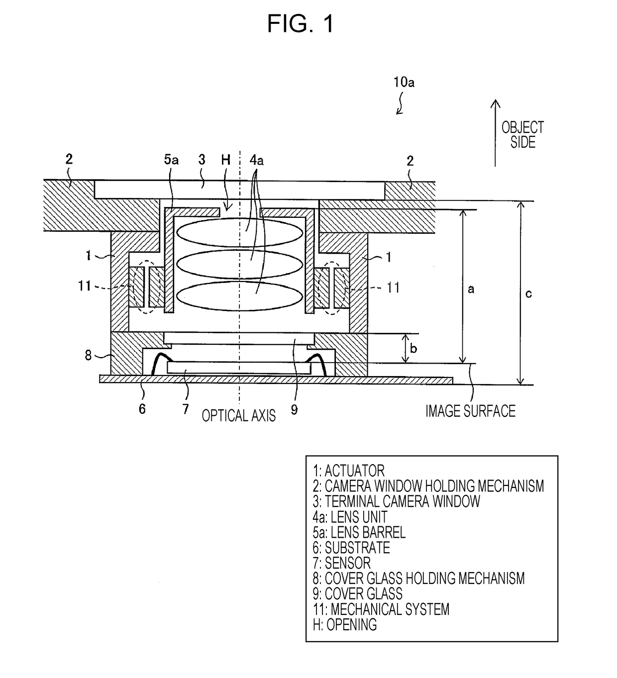
[0035]FIG. 2 is a sectional view illustrating a structure of a camera module 10b according to Embodiment 2 of the present invention. The camera module 10b of the present embodiment is different from the camera module 10a described above in that the lenses on the object side of the lens unit 4b have smaller diameters than other lenses, and the wall surface (the receiving portion of the camera window holding mechanism 2) of the opening H of the camera window holding mechanism 2 is close to edge portions K of the lenses on the object side of the lens unit 4b. PTL 2 discloses a configuration for reducing the size, by accommodating an actuator in a portion having a smaller diameter by using a difference between the effective lens diameters. However, in the present embodiment, the camera window holding mechanism 2 fills a vacant space provided as a result of reducing the diameter of the lenses on the object side, and the opening window size (the size of the opening H) is reduc...
Example
Embodiment 3
[0037]FIG. 3 is a sectional view illustrating a structure of a camera module 10c according to Embodiment 3 of the present invention. The camera module 10c of the present embodiment is different from the camera module 10a described above in that a camera window holding mechanism 2R is disposed, by partially varying the thickness in the optical axis direction of the camera window holding mechanism, for non-rotational symmetrical actuators 1L, 1R (in FIG. 3, a mechanical system 11L is present only on the left side of paper and a mechanical system is not present on the right side). For the convenience, a portion present on the right side in paper, of the camera window holding mechanism illustrated in FIG. 3, is referred to as a camera window holding mechanism 2R, and a portion present on the left side is referred to as a camera window holding mechanism 2L. In this case, the thickness in the optical axis direction of the camera window holding mechanism 2R is thicker than the ...
PUM
 Abstract
Description
Claims
Application Information
 - R&D Engineer
- R&D Manager
- IP Professional
- Industry Leading Data Capabilities
- Powerful AI technology
- Patent DNA Extraction
Browse by: Latest US Patents, China's latest patents, Technical Efficacy Thesaurus, Application Domain, Technology Topic.
© 2024 PatSnap. All rights reserved.Legal|Privacy policy|Modern Slavery Act Transparency Statement|Sitemap