Dual-purpose locking and folding arrangement for an aircraft wing tip device

a technology of locking and folding arrangement and aircraft wing tip, which is applied in the direction of airflow influencers, wing adjustments, aircraft transmission means, etc., can solve the problem of effectively limited maximum aircraft span, and achieve the effect of reducing static bending moment, and easily unlocked

Active Publication Date: 2017-06-01
AIRBUS OPERATIONS LTD
View PDF3 Cites 6 Cited by
  • Summary
  • Abstract
  • Description
  • Claims
  • Application Information

AI Technical Summary

Benefits of technology

[0009]The wing tip device may be rotatable about a hinge. The wing tip device may be rotatable (about the hinge) in an upward direction, when moving from the flight configuration to the ground configuration. The wing tip device may generate a static (i.e. 1 g) bending moment about the hinge. The wing tip device may be moveable between the flight and ground configurations about a hinge and in the flight configuration the wing tip device may generate a static bending moment about the hinge, and the first actuator stage may be arranged to at least partially relieve the static bending moment, prior to unlocking the lock. At least partially relieving the static bending moment, prior to unlocking the lock, may enable the lock to be more readily unlocked.

Problems solved by technology

However, the maximum aircraft span is effectively limited by airport operating rules which govern various clearances required when manoeuvring around the airport (such as the span and / or ground clearance required for gate entry and safe taxiway usage).

Method used


Image

  • Dual-purpose locking and folding arrangement for an aircraft wing tip device
  • Dual-purpose locking and folding arrangement for an aircraft wing tip device
  • Dual-purpose locking and folding arrangement for an aircraft wing tip device

Examples


Embodiment Construction

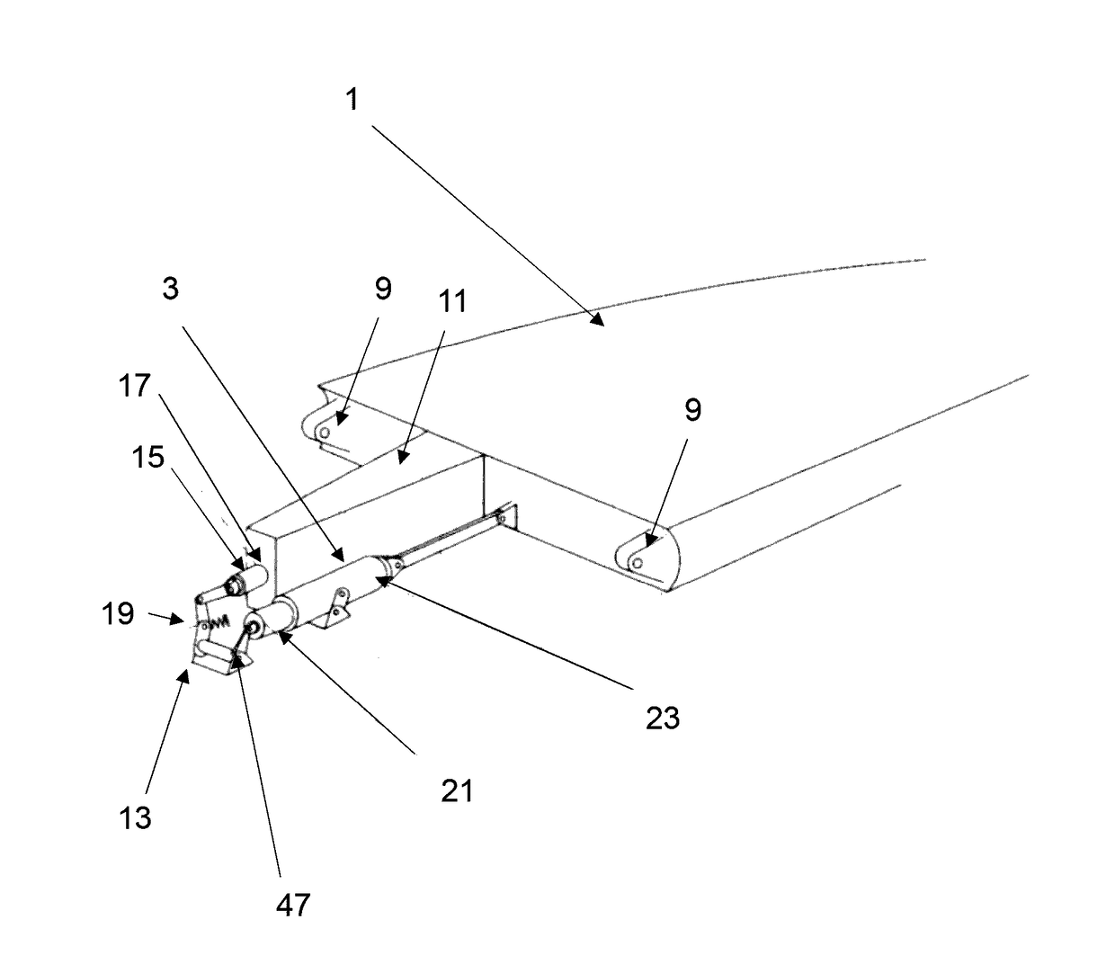
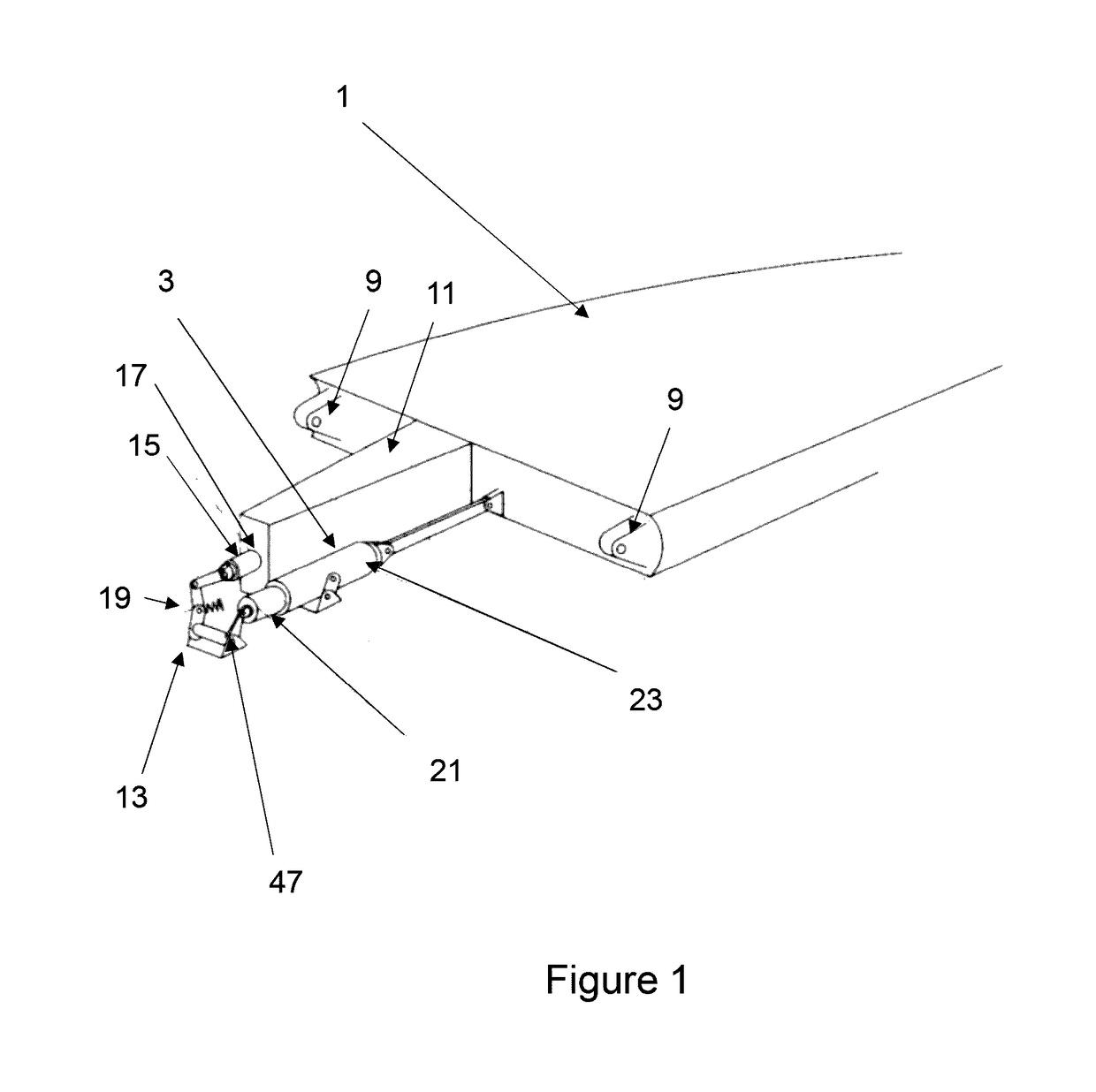
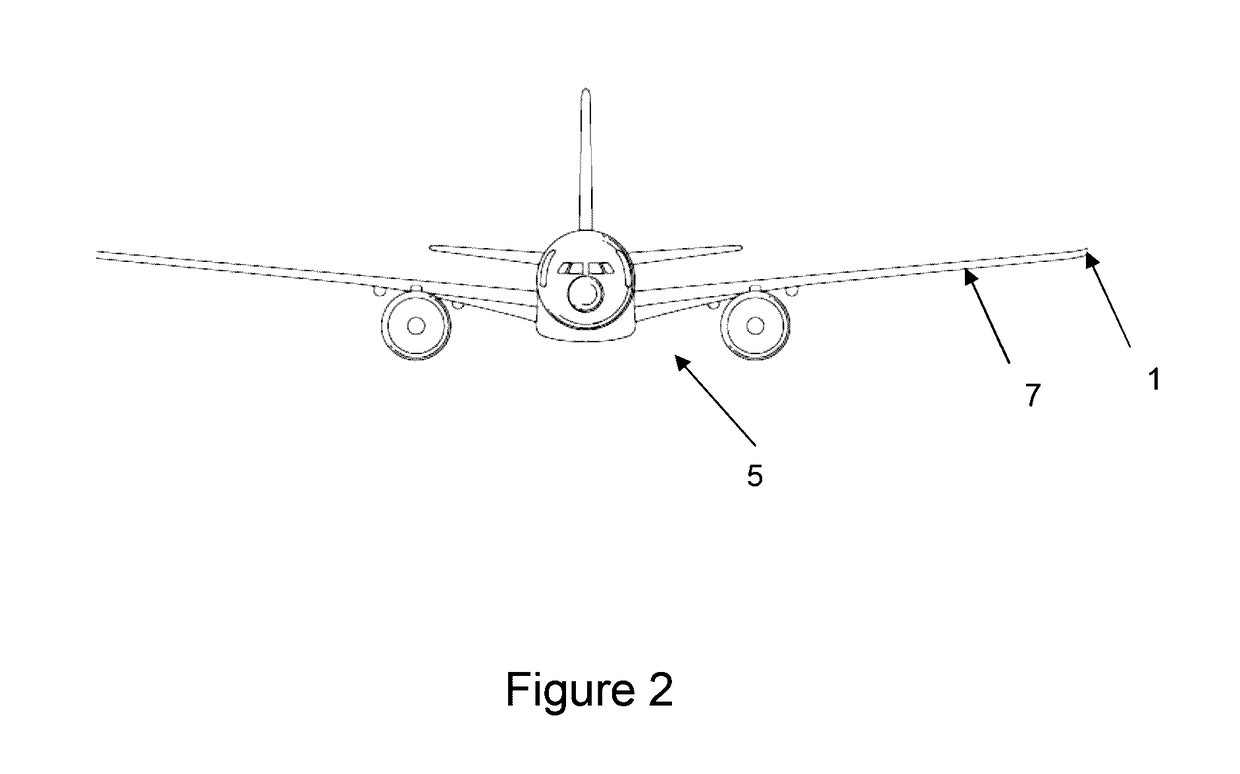
[0032]FIG. 1 shows a wing tip device 1 and two-stage actuator 3 for use on an aircraft 5 according to a first embodiment of the invention. The aircraft 5 is shown in FIG. 2, but for clarity, only the wing tip device 1 and actuator 3 are shown in FIG. 1.

[0033]The wing tip device 1 is a planar wing tip extension, which is mounted to the tip of a fixed aircraft wing 7 via a hinge 9 (only the lugs of the hinge are shown in FIG. 1). The wing tip device 1 is configurable from a flight configuration in which the wing tip device 1 is an extension of the fixed wing 7 (i.e. as shown in FIGS. 1 and 2), to a ground configuration (not shown) in which the wing tip device 1 is pivoted upwardly about the hinge 9. The upward folding of the wing tip device 1 enables the span of the aircraft to be reduced, to meet airport gate limits for example.

[0034]The wing tip device 1 comprises a stub spar 11 which extends inboard of the hinge 9. At the inboard end of the stub spar 11 is a locking mechanism 13. T...


PUM


Abstract

An aircraft (5) including a wing (7) having a wing tip device (1) configurable between: a flight configuration and a ground configuration in which the span of the wing (7) is reduced. The aircraft (5) further includes a lock (13) for locking the wing tip device (1) in the flight configuration, and an actuator (3) for unlocking the lock (13) and for subsequently actuating the wing tip device (1) to the ground configuration. The actuator (3) is a two-stage hydraulic actuator, including a first hydraulic actuator stage (21) arranged to unlock the lock and a second hydraulic actuator stage (23) arranged to actuate the wing tip device (1) to the ground configuration. The first and second hydraulic actuator stages (21, 23) are arranged in series such that the second actuator stage (23) is unable to receive a hydraulic input feed until the first actuator stage (21) unlocks the lock (13).

Description

CROSS RELATED APPLICATION[0001]This application claims priority to Great Britain patent application 1521091.7 filed Nov. 30, 2015, the entirety of which is incorporated by reference.BACKGROUND OF THE INVENTION[0002]There is a trend towards increasingly large passenger aircraft, for which it is desirable to have correspondingly large wing spans. However, the maximum aircraft span is effectively limited by airport operating rules which govern various clearances required when manoeuvring around the airport (such as the span and / or ground clearance required for gate entry and safe taxiway usage).[0003]To address this problem, aircraft having so-called folding wing tips have been suggested. For example, a previously-suggested arrangement comprises an aircraft having a wing tip device that may be configurable between: (i) a flight configuration for use during flight, and (ii) a ground configuration for use during ground-based operations. In the ground configuration, the wing tip device is...

Claims


Application Information

Patent Timeline
Patent Type & Authority Applications(United States)
IPC IPC(8): B64C3/56F15B15/14B64C13/40
CPCB64C3/56B64C13/40F15B15/1409F15B2211/7055F15B15/1428F15B2211/40F15B15/1447B64C23/072F15B11/205F15B15/1404Y02T50/10
Inventor WILSON, FRASERTHOMPSON, ROBERT IAN
Owner AIRBUS OPERATIONS LTD
Why Eureka
Try Eureka