Lamination structure and a method for manufacturing the same
a technology of lamination structure and manufacturing method, which is applied in the field of lamination structure, can solve problems such as scratches or dents in objects
- Summary
- Abstract
- Description
- Claims
- Application Information
AI Technical Summary
Benefits of technology
Problems solved by technology
Method used
Image
Examples
first embodiment
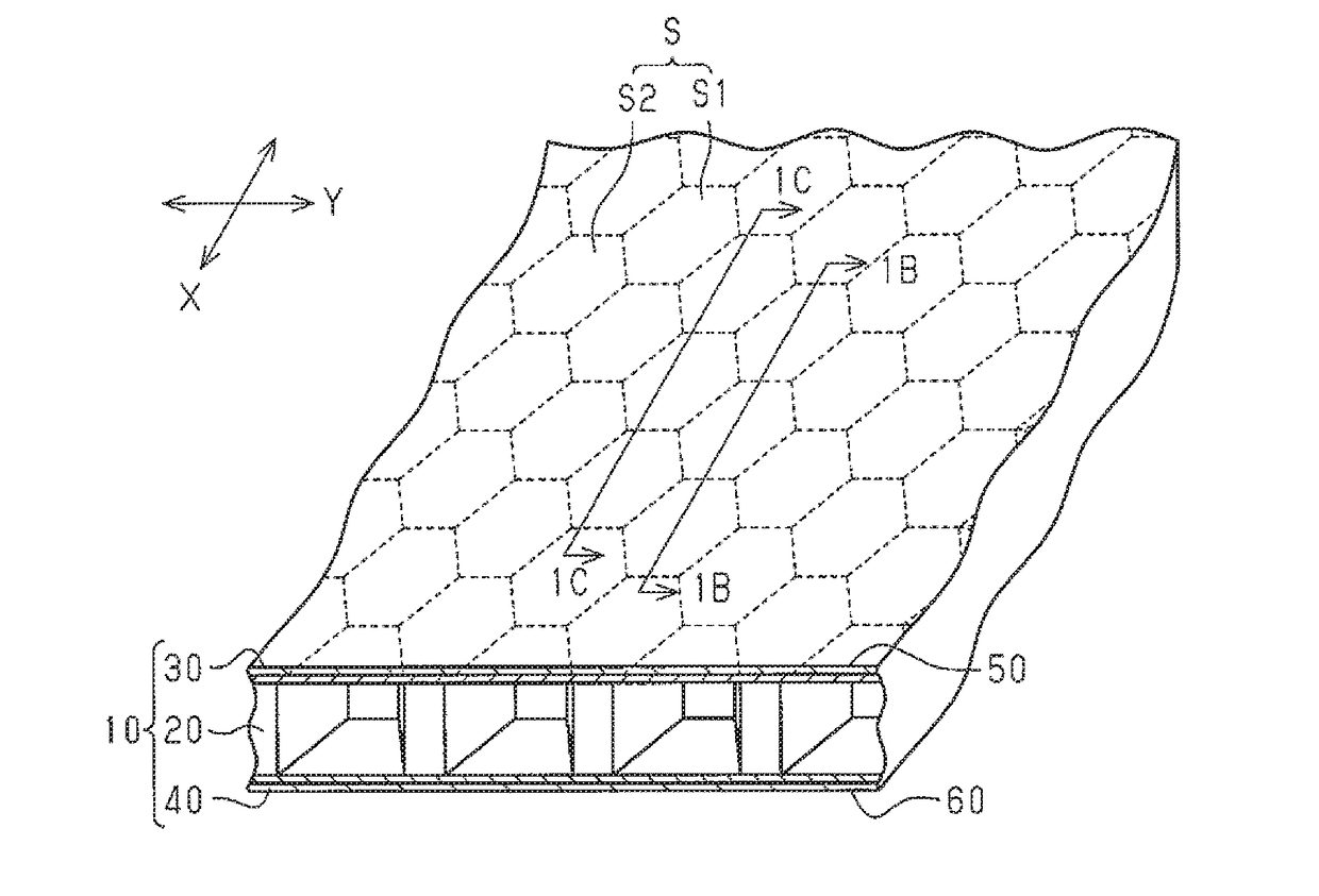
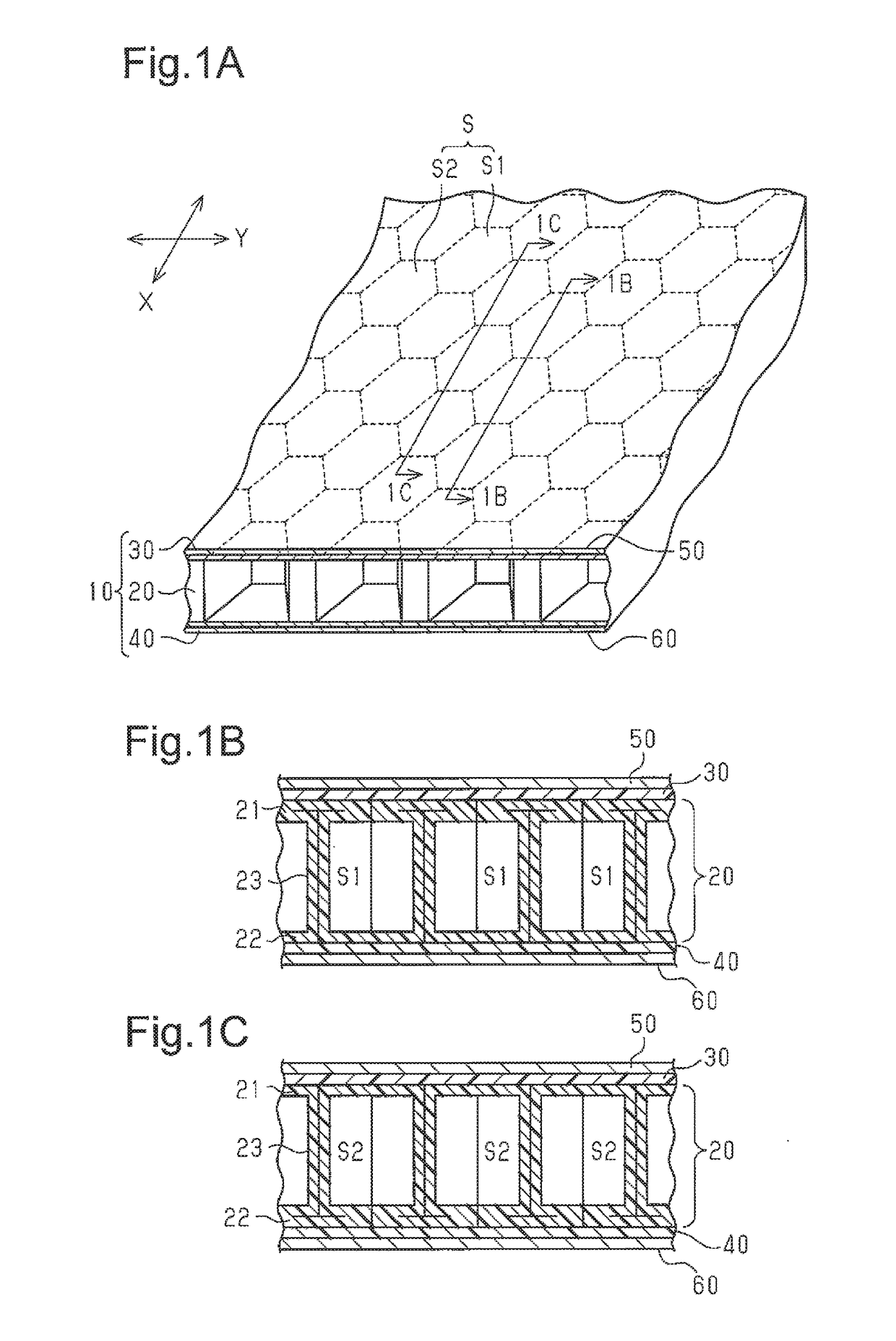
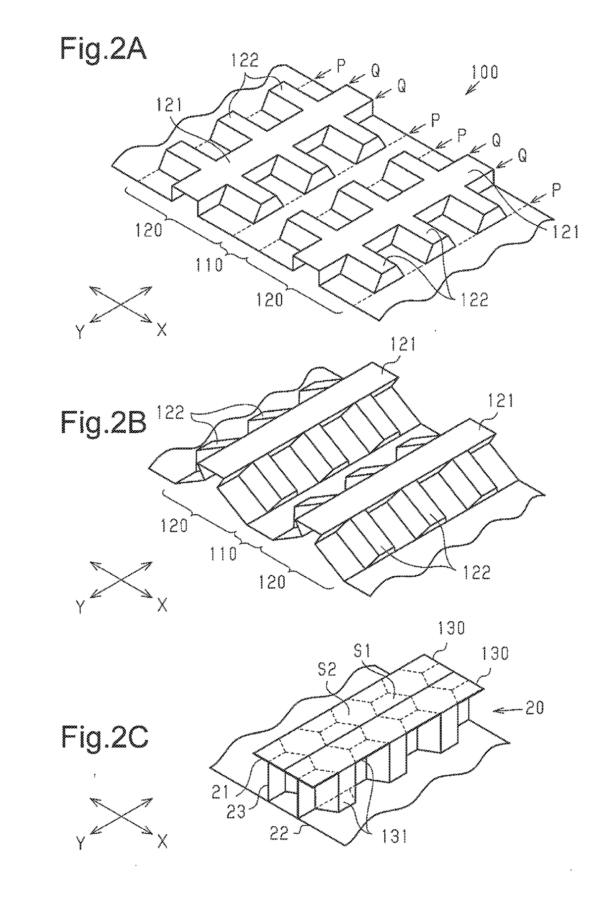
[0045]Referring to FIGS. 1A to 3I, a first embodiment of a lamination structure according to the present invention and a method for manufacturing the same will now be described.
[0046]As shown in FIG. 1A, the lamination structure includes a hollow plate 10, which has the shape of a hollow plate as a whole, and metal plates 50 and 60, which are placed on the upper and lower sides of the hollow plate 10. As shown in FIG. 1A, the hollow plate 10 includes a core layer 20, in which cells S are arranged side by side, and sheet-shaped superficial layers 30 and 40, which are bonded to the upper and lower sides of the core layer 20.
[0047]Referring to FIGS. 1B and 1C, the core layer 20 is formed by folding a single sheet member, which is made of a thermoplastic resin and has a predetermined shape. The core layer 20 includes upper walls 21, lower walls 22, and side walls 23. The side walls 23 extend between the upper walls 21 and the lower walls 22 and define cells S inside the core layer 20. E...
second embodiment
[0097]Referring to FIGS. 4A to 6C, a second embodiment of a lamination structure and a method for manufacturing the same according to the present invention will now be described. The components of the second embodiment that are the same as the corresponding components of the first embodiment will not be described in detail.
[0098]As shown in FIGS. 4A to 4C, the periphery of a hollow plate 310 includes a sealing section 311 that seals the hollow plate 310 so that the internal cavities of the cells S are not exposed to the outside. The sealing section 311 is formed by heating and compressing the periphery of the hollow plate 310 inward. As such, the sealing section 311 is formed integrally with the hollow plate 310 from the thermoplastic resin forming the core layer 320 and the superficial layers 330 and 340 of the hollow plate 310. The sealing section 311 is formed over the entire circumference of the hollow plate 310.
[0099]The sealing section 311 has a tetragonal cross-section as a w...
third embodiment
[0138]Referring to FIGS. 9 to 13C, a third embodiment of a lamination structure and a method for manufacturing the same according to the present invention will now be described. The components of the third embodiment that are the same as the corresponding components of the foregoing embodiments will not be described in detail.
[0139]As shown in FIG. 9, the upper surface of a lamination structure, that is, the upper surface of an upper metal plate 650, includes a recess 670. The recess 670 is rectangular as viewed from above. The recess 670 includes four side walls 671, which extend downward from a surface 652 of the upper metal plate 650, and a rectangular base wall 672, which is surrounded by the side walls 671. The side walls 671 are substantially at a right angle to the surface 652 of the upper metal plate 650, and the base wall 672 is substantially at a right angle to the side walls 671.
[0140]As shown in FIG. 10A, the upper metal plate 650 includes a metal recess 651. The metal r...
PUM
| Property | Measurement | Unit |
|---|---|---|
| thickness | aaaaa | aaaaa |
| thickness | aaaaa | aaaaa |
| distance | aaaaa | aaaaa |
Abstract
Description
Claims
Application Information
 - R&D
- Intellectual Property
- Life Sciences
- Materials
- Tech Scout
- Unparalleled Data Quality
- Higher Quality Content
- 60% Fewer Hallucinations
Browse by: Latest US Patents, China's latest patents, Technical Efficacy Thesaurus, Application Domain, Technology Topic, Popular Technical Reports.
© 2025 PatSnap. All rights reserved.Legal|Privacy policy|Modern Slavery Act Transparency Statement|Sitemap|About US| Contact US: help@patsnap.com


