Vehicular fuel cell system and method of controlling the same

a fuel cell and vehicle technology, applied in the direction of battery/fuel cell control arrangement, vehicle sub-unit features, electric devices, etc., can solve the problems of insufficient shut-off of the fuel supply to the fuel cell stack, failure of the controller, and failure to function properly, so as to achieve the effect of reliably stopping the function of the control targ

Active Publication Date: 2017-06-22
TOYOTA JIDOSHA KK
View PDF2 Cites 2 Cited by
  • Summary
  • Abstract
  • Description
  • Claims
  • Application Information

AI Technical Summary

Benefits of technology

[0009]According to this aspect, in a case where collision occurs on one side of the vehicle, and the high voltage controller on one side fails, the supply valve controller which is at a location separated from the collision part on the other side of the vehicle unsusceptible to an impact of collision reliably performs the discharging control for discharging the high voltage unit. Furthermore, in a case where collision occurs on the other side of the vehicle, and the supply valve controller on the other side fails, the high voltage controller which is at a location separated from the collision part on one side of the vehicle unsusceptible to an impact of collision reliably performs the shutoff control for bringing the hydrogen supply valve into the closed state. That is, it is possible to reliably stop the function of a control target even in a case where vehicle collision occurs.
[0013]With this, when collision on one side is detected, it is possible to give a user notification to the effect that the vehicle is in the traveling-disabled state and to prevent unreasonable retreat traveling while reliably performing the discharging control of the high voltage unit on one side.
[0019]According to the disclosure, it is possible to provide a vehicular fuel cell system and a method of controlling the same capable of reliably stopping the function of a control target even in a case where vehicle collision occurs.

Problems solved by technology

If collision at the front or rear of the vehicle occurs, the controllers may fail and may not function.
In this case, there is a concern that shut-off of the fuel supply to the fuel cell stack and shut-off of the power system of the fuel cell stack are not properly performed.

Method used


Image

  • Vehicular fuel cell system and method of controlling the same
  • Vehicular fuel cell system and method of controlling the same
  • Vehicular fuel cell system and method of controlling the same

Examples


first embodiment

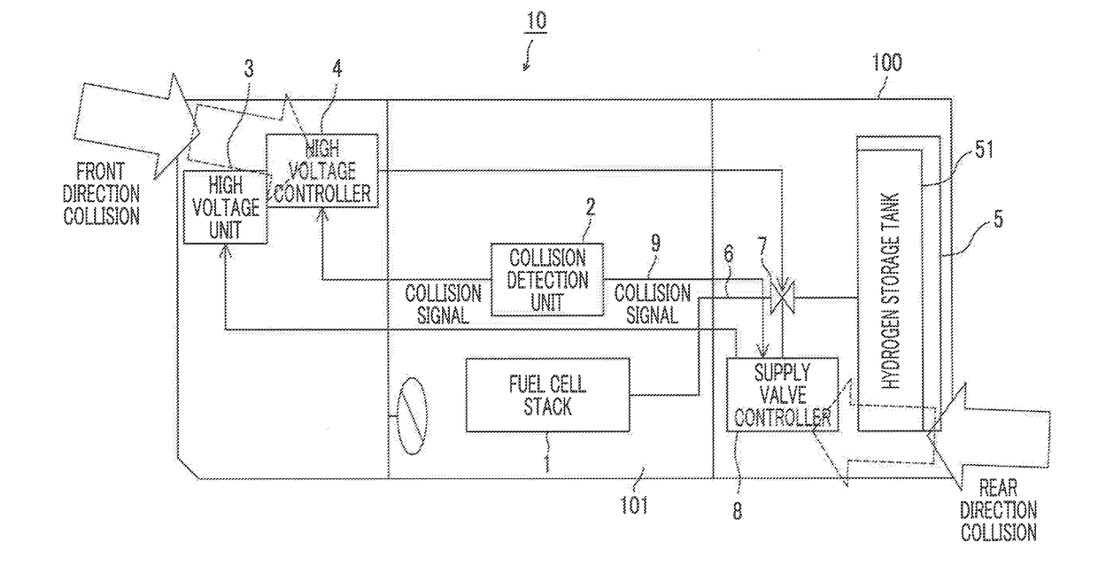
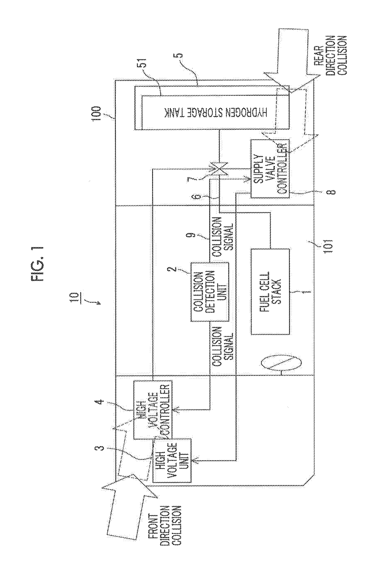
[0026]Hereinafter, an embodiment of the disclosure will be described referring to the drawings. FIG 1 is a block diagram showing a schematic system configuration of a vehicular fuel cell system according to a first embodiment.

[0027]A vehicular fuel cell system 10 according to the first embodiment is mounted in a fuel cell vehicle 100 in which a fuel cell stack 1 is mounted as an on-vehicle power supply. The vehicular fuel cell system 10 according to the first embodiment includes a collision detector 2 which detects collision on the front and rear sides of the vehicle, a high voltage unit 3 (in this embodiment, a battery) which is arranged on one side of the front and rear sides of the vehicle and has a high voltage, a high voltage controller 4 which is arranged on one side and controls the high voltage unit 3, a hydrogen supply unit 5 which is arranged on the other side of the front and rear sides of the vehicle and supplies hydrogen to the fuel cell stack 1, and a supply valve cont...

second embodiment

[0051]FIG. 3 is a block diagram showing a schematic system configuration of a vehicular fuel cell system 20 according to a second embodiment of the disclosure. In the second embodiment, a plurality of proximity sensors 21 which detect distance information with respect to an object are provided on the front and rear sides of the vehicle in the periphery of the vehicle. The proximity sensors 21 are, for example, ultrasonic sensors, radar sensors, or the like. For example, a pair of proximity sensors 21 are provided near both ends of the front side of the vehicle (a front bumper or the like) and a pair of proximity sensors 21 are provided near both ends of the rear side of the vehicle (a rear bumper or the like). The locations and the number of proximity sensors 21 provided in the periphery of the vehicle are arbitrarily determined as long as the proximity sensors 21 are respectively provided on the front and rear sides of the vehicle.

[0052]On the front side of the vehicle, a proximity...

third embodiment

[0059]FIG. 4 is a block diagram showing a schematic system configuration of a vehicular fuel cell system according to a third embodiment of the disclosure. A vehicular fuel cell system 30 according to the third embodiment further includes a traveling determination unit 31 which determines whether or not the vehicle is travelable after vehicle collision, in addition to the configuration according to the second embodiment described above.

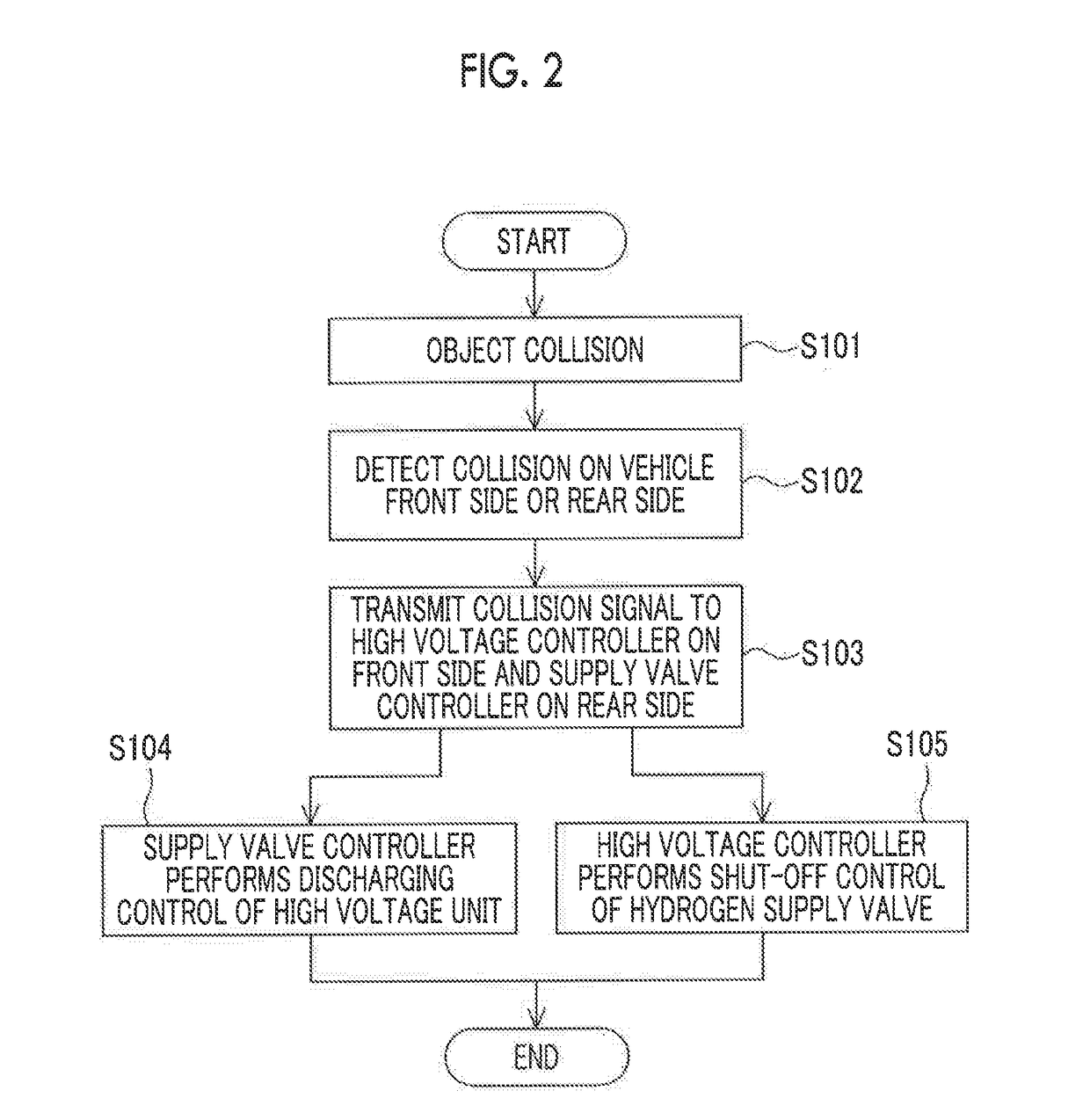
[0060]In a case where collision actually occurs, as described above, it is necessary to not only stop the function of a required control target, such as the discharging control of the high voltage unit 3, or the shut-off control of the hydrogen supply valve 7, but also quickly retreat the vehicle from a collision place (a traveling lane of an expressway, an intersection with heavy traffic, or the like). However, there are a case where retreat traveling should be performed and a case where retreat traveling should not be performed according to the loca...


PUM

PropertyMeasurementUnit
voltageaaaaaaaaaa
distanceaaaaaaaaaa
accelerationaaaaaaaaaa

Abstract

A vehicular fuel cell system includes a collision detector configured to detect collision on the front and rear sides of a vehicle, a high voltage unit arranged on one side of the front and rear sides of the vehicle, a high voltage controller arranged on the one side and configured to control the high voltage unit, a hydrogen supply unit arranged on the other side of the front and rear sides of the vehicle and configured to supply hydrogen to a fuel cell stack, and a supply valve controller arranged on the other side and configured to control a hydrogen supply valve, the hydrogen supply valve being configured to shut off a supply path of hydrogen from the hydrogen supply unit to the fuel cell stack.

Description

[0001]The disclosure of Japanese Patent Application No. 2015-245902 filed on Dec. 17, 2015 including the specification, drawings and abstract is incorporated herein by reference in its entirety.BACKGROUND[0002]1. Technical Field[0003]The disclosure relates to a vehicular fuel cell system and a method of controlling the same.[0004]2. Description of Related Art[0005]For example, a vehicular fuel cell system which, if collision of a vehicle is detected, shuts off the fuel supply to a fuel cell stack by a shut-off valve and shuts off a power system of the fuel cell stack by a relay is known (see Japanese Patent Application Publication No. 2007-335184 (JP 2007-335184 A)).SUMMARY[0006]However, in the above-described vehicular fuel cell system, for example, a controller which controls the relay of the power system and a controller which controls the shut-off valve of the fuel supply are respectively arranged at the front or rear of the vehicle. If collision at the front or rear of the vehi...

Claims


Application Information

Patent Timeline
Patent Type & Authority Applications(United States)
IPC IPC(8): B60L3/00H01M8/04746H01M16/00H01M8/04955
CPCB60L3/0053H01M8/04955H01M2250/20H01M16/006B60L3/0007H01M8/04753B60L58/31B60L58/30B60L3/0084B60L3/04H01M8/04089H01M8/04313H01M8/04664B60L50/72Y02T90/40Y02T10/70Y02E60/50Y02E60/10B60L50/71B60Y2400/3042
Inventor TSUTSUI, TOKURO
Owner TOYOTA JIDOSHA KK
Why Eureka
Try Eureka