Vent system for an axle and hub assembly

a technology of exhaust system and hub assembly, which is applied in the direction of hubs, wheel bearings, transportation and packaging, etc., can solve the problems of increasing ambient pressure in the cavity, shortening the life of the wheel bearing, and increasing the pressure in the cavity of the wheel hub, etc., to damage the related components

Inactive Publication Date: 2001-12-04
DANA CORP
View PDF16 Cites 34 Cited by
  • Summary
  • Abstract
  • Description
  • Claims
  • Application Information

AI Technical Summary

Benefits of technology

Another object of the present invention is to provide a filtered venting system that is contained within the axle and spindle, wherein the system allows the use of simple and inexpensive non-vented hub caps.
These as well as additional objects and advantages of the present invention are achieved by providing a filtered vent at the wheel end cavity (i.e., the filtered spindle plug) as well as a second one-way, check valve vent directly from the axle tube to atmosphere to provide pressure relief. The filtered passage extending through the spindle plug and the vented axle tube equalize the pressure between the wheel hub cavity and the outside environment. The filtered spindle plug is provided with a porous material which allows a flow of gases through the passage while preventing liquids and other contaminants from traveling therethrough, wherein the axle tube is further provided with a vent to the atmosphere through a one-way pressure relief valve located in the axle tube.

Problems solved by technology

External contaminants can substantially shorten the life of the wheel bearings.
Friction resulting from the rotating bearings heats the lubricant and the air space within the hubcap causing the enclosed lubricant and air to expand, thereby increasing ambient pressure in the cavity.
This increased pressure in the wheel hub cavity can become great enough to damage related components such as the oil seal the seal between the hubcap and the wheel hub or even the hubcap itself.
Damage to these components can cause leakage of lubricant from the wheel hub cavity and hubcap, resulting in insufficient bearing lubrication.
Moreover, with non-driving axles having hollow spindles, there is a tendency for moisture and condensation to build up in the axle tube during use.
Thus, while the hub cap may prevent entry of some contaminants, it does not prevent the build up of moisture and debris in the axle tube and the wheel end cavity.
However, these valve vent devices also permit lubricant flow out of the hubcap during venting, this results in excessive loss of lubricant over time.
In addition, these devices are often unduly complicated because they utilize numerous parts and, therefore, are relatively expensive to manufacture.
However, these devices are secured in a vent passage formed in the hubcap via an interference or press fit which requires precision machining to ensure the low tolerances necessary for a secure fit.
It is well known, however, that precision machining also results in increased manufacturing costs.
Further, the outer surfaces of the prior art vent plugs are directly exposed to the outside work environment and therefore may become undesirably blocked by grit and other contaminants, severely hindering the venting action of the porous material.

Method used


Image

  • Vent system for an axle and hub assembly
  • Vent system for an axle and hub assembly
  • Vent system for an axle and hub assembly

Examples


Embodiment Construction

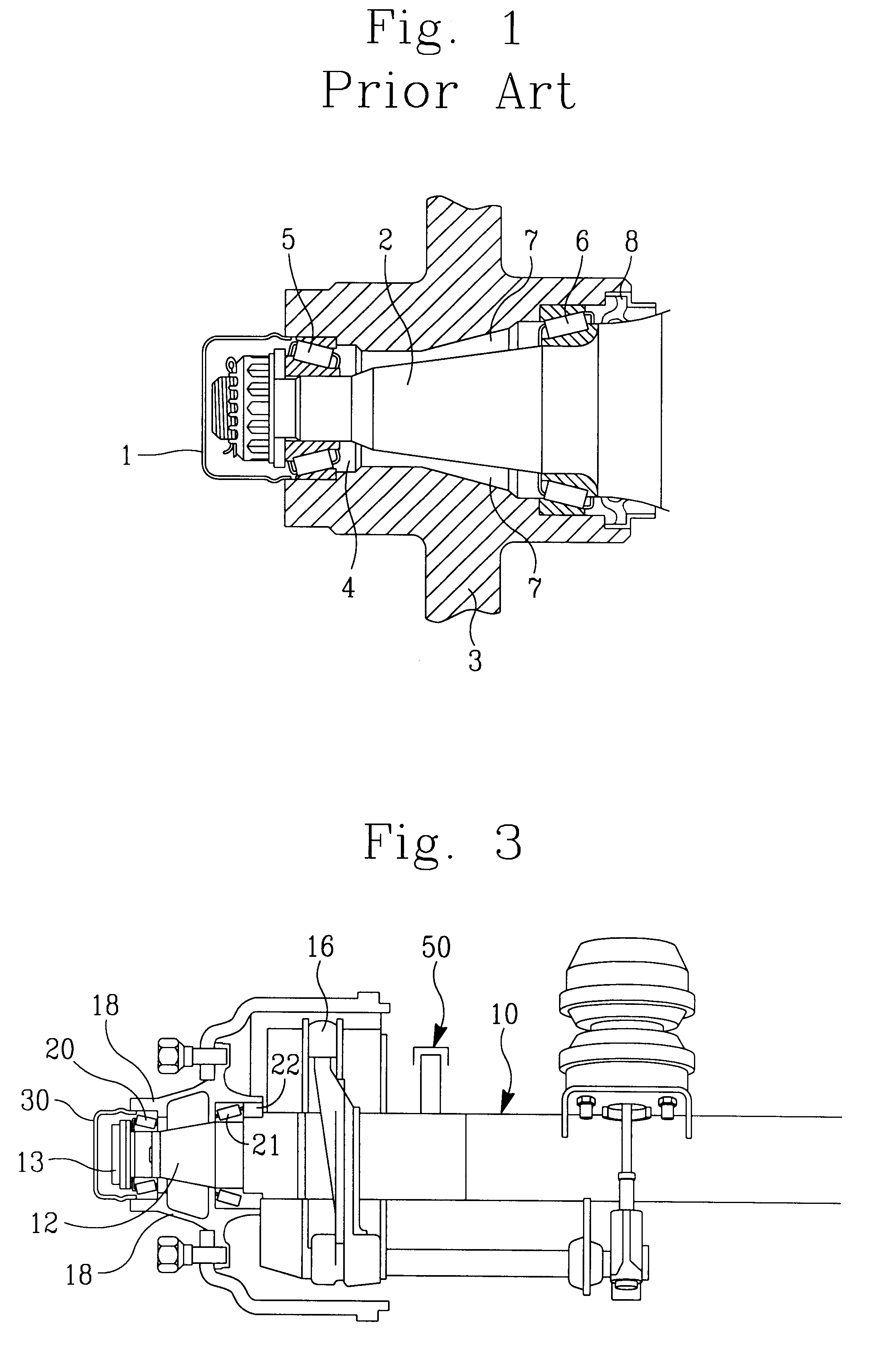
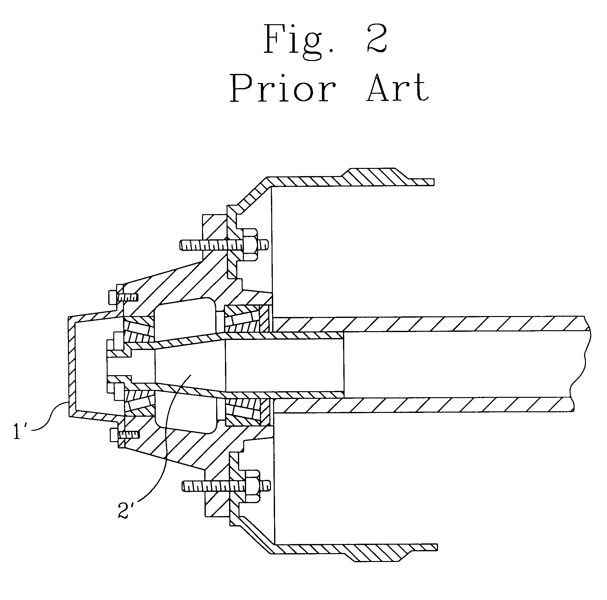
FIG. 1 shows a conventional freewheeling or non-driving wheel bearing assembly for a front or rear axle of a vehicle. As shown in FIG. 1, two tapered wheel bearings 5, 6 allow the hub 3 and wheel (not shown) to rotate around a stationary solid spindle 2. Grease or lubricant 4 partially fills the hub to lubricate the bearings 5, 6, and the seal 8 prevents loss of lubricant. A dust cap or hub cap 1 fits over the outer end of the hub to keep the grease in and road dirt out of the bearings 5, 6 and the wheel end cavity 7. FIG. 2 shows a conventional hollow, non-driving wheel assembly comprising a hollow spindle 2' and a hubcap 1' attached to the wheel hub via bolts or the like. With this conventional design, the vented hubcap 1' or a vented plug has been disposed at the end of the hollow spindle.

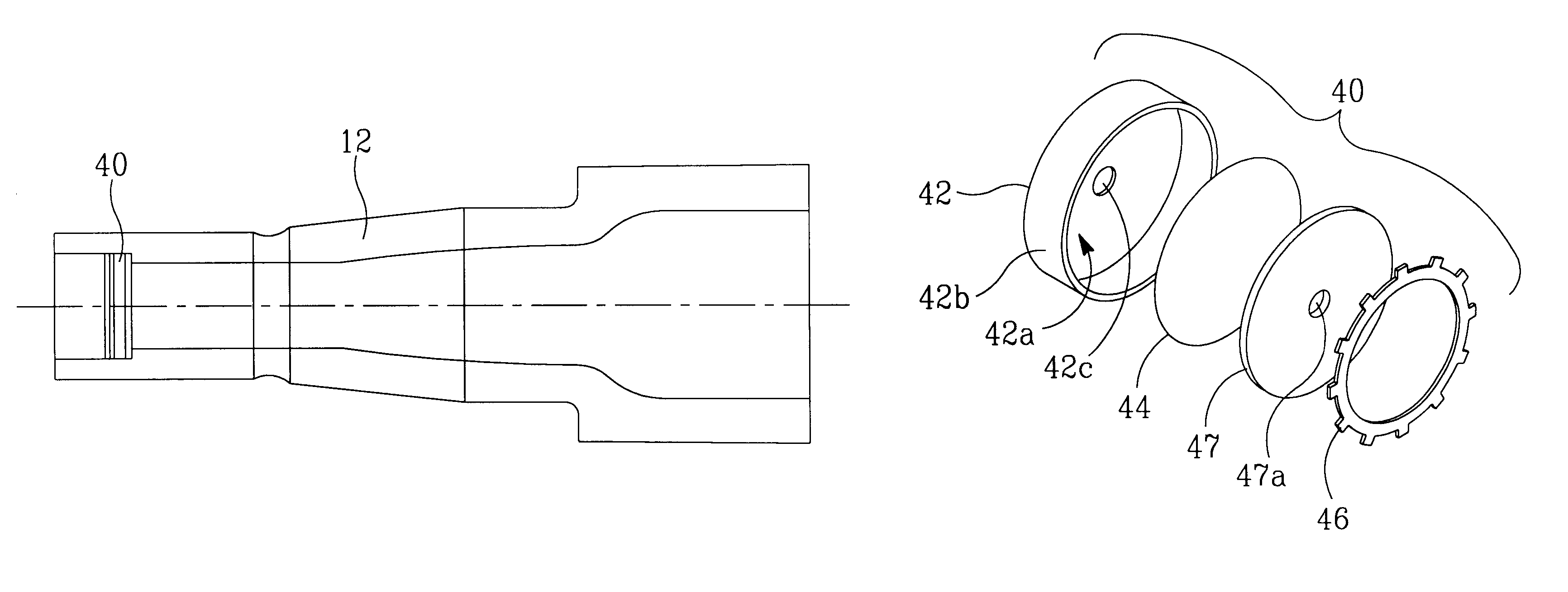
FIG. 3 shows a non-driving axle consisting of a tube and hollow spindles as shown in FIG. 4. The spindles 12 are typically fitted with a plug having a small hole in the center. With this axle de...


PUM


Abstract

A vent system for a wheel hub comprising a first filtered vent at the wheel end cavity and a second vent formed by a one-way, pressure relief valve venting the axle tube to atmosphere. The vent system defines a vent path from the wheel end cavity through a first, preferably filtered, vent into the axle tube then through a second check valve connecting the axle tube to atmosphere. A porous material is positioned to cover the vent passage at the wheel end cavity for allowing a flow of gases to enter and exit the vent passage while preventing liquids and other contaminants from traveling therethrough. The porous material is held in place over the vent by a snap ring or other suitable retention system disposed within the vented plug member. The second axle tube vent is disposed along the axle tube to vent the tube itself to atmosphere with pressure relief

Description

1. Technical FieldThe present invention relates to an venting system and more particularly to an venting system for use with a wheel bearing and lubrication system.2. Background ArtIn translational and rotational devices generally and particularly on the wheels of most vehicles such as trucks and trailers, hubcaps are used to maintain oil or grease in the wheel bearings. In addition, hubcaps help exclude external contaminants and prevents them from coming into contact with the wheel bearings within the wheel hub cavity. External contaminants can substantially shorten the life of the wheel bearings.The interior of the wheel hub cavity is partially filled with oil or grease so that the wheel bearings are lubricated. Friction resulting from the rotating bearings heats the lubricant and the air space within the hubcap causing the enclosed lubricant and air to expand, thereby increasing ambient pressure in the cavity. The characteristic "pumping" action normally associated with the opera...

Claims


Application Information

Patent Timeline
Patent Type & Authority Patents(United States)
IPC IPC(8): B60B35/00
CPCB60B7/002B60B7/066B60B7/14B60B27/02B60B35/025B60B27/0005B60B2360/32B60B2380/14B60B2900/321B60B2900/325B60B2900/561B60Y2200/147B60Y2200/221
Inventor SITTER, DONDAVISON, KENTBLESSING, MARTIN G.
Owner DANA CORP
Why Eureka
Try Eureka