Eureka AIR delivers breakthrough ideas for toughest innovation challenges, trusted by R&D personnel around the world.

Apparatuses and methods for making glued screen assemblies

a technology of glued screens and assemblies, applied in the direction of moving filter elements, separation processes, filtering separation, etc., can solve the problems of increasing wear on mud pumps and other mechanical equipment used for drilling, increasing the viscosity of mud, and weight, etc., and reducing the viscosity of at least lower portions

Inactive Publication Date: 2004-12-16
VARCO I P INC
View PDF99 Cites 37 Cited by
  • Summary
  • Abstract
  • Description
  • Claims
  • Application Information

AI Technical Summary

Benefits of technology

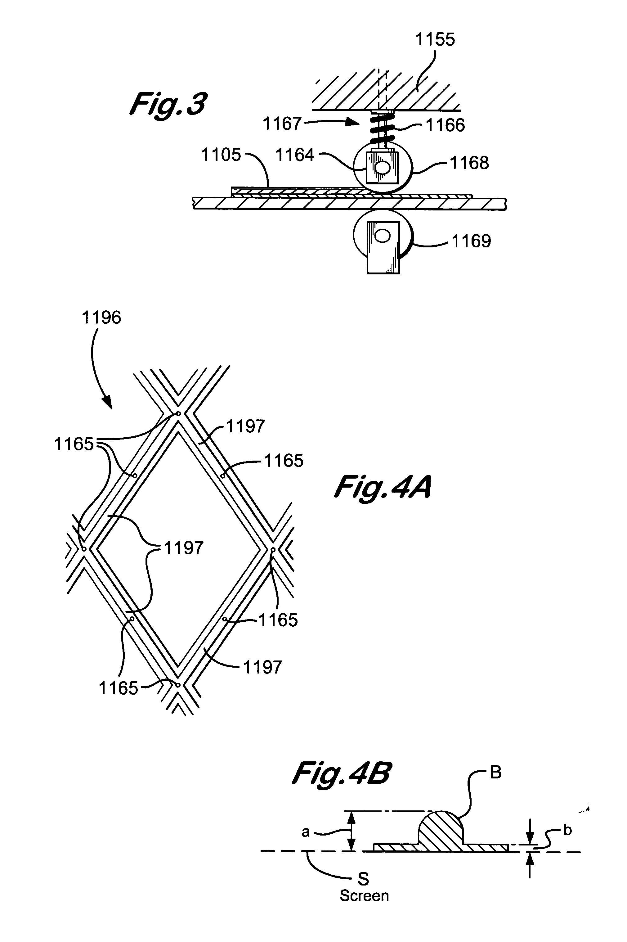
[0011] In certain aspects, using a "nip" or dual opposed rollers (optionally under pressure) between which multiple screen layers being glued together are passed, glue moves and / or is squeezed upwardly between mesh in the screening layers. In one aspect a bottom nip roller (in one embodiment coated with a non-stick substance or tape) pushes up against a lower surface of a bottommost screen layer, preventing glue from moving down and out from the screen layer. Optionally, such a bottom roller may be cooled (by any known method and / or device or apparatus, including but not limited to, those disclosed or referred to herein), thus increasing the viscosity of at least lower portions, if not a large portion of the glue and inhibiting downward travel of the glue. The wires or strands of the mesh(es) restrict side-to-side glue movement and the glue, therefore, can only travel up into layers above a layer or layers to which the glue was initially applied. Optionally, the top roller is heated by any known method and / or device or apparatus (including, but not limited to, any disclosed or referred to herein), which heats upper parts and / or layers of mesh(es) which results in the heating of upper portions of glue that has been applied to one or more layers, thus reducing the viscosity of these portions and facilitating upward passage of the glue through the upper layer(s) of screening material. Optionally the two rollers are forced together (in one aspect a pressure between about twenty to about fifty p.s.i.) squeezing screening layers together and forcing glue to move up through the mesh of the layers.

Problems solved by technology

If drilled solids are not removed from the mud used during the drilling operation, recirculation of the drilled solids can create weight, viscosity, and gel problems in the mud, as well as increasing wear on mud pumps and other mechanical equipment used for drilling.

Method used


Image

  • Apparatuses and methods for making glued screen assemblies
  • Apparatuses and methods for making glued screen assemblies
  • Apparatuses and methods for making glued screen assemblies

Examples


Embodiment Construction

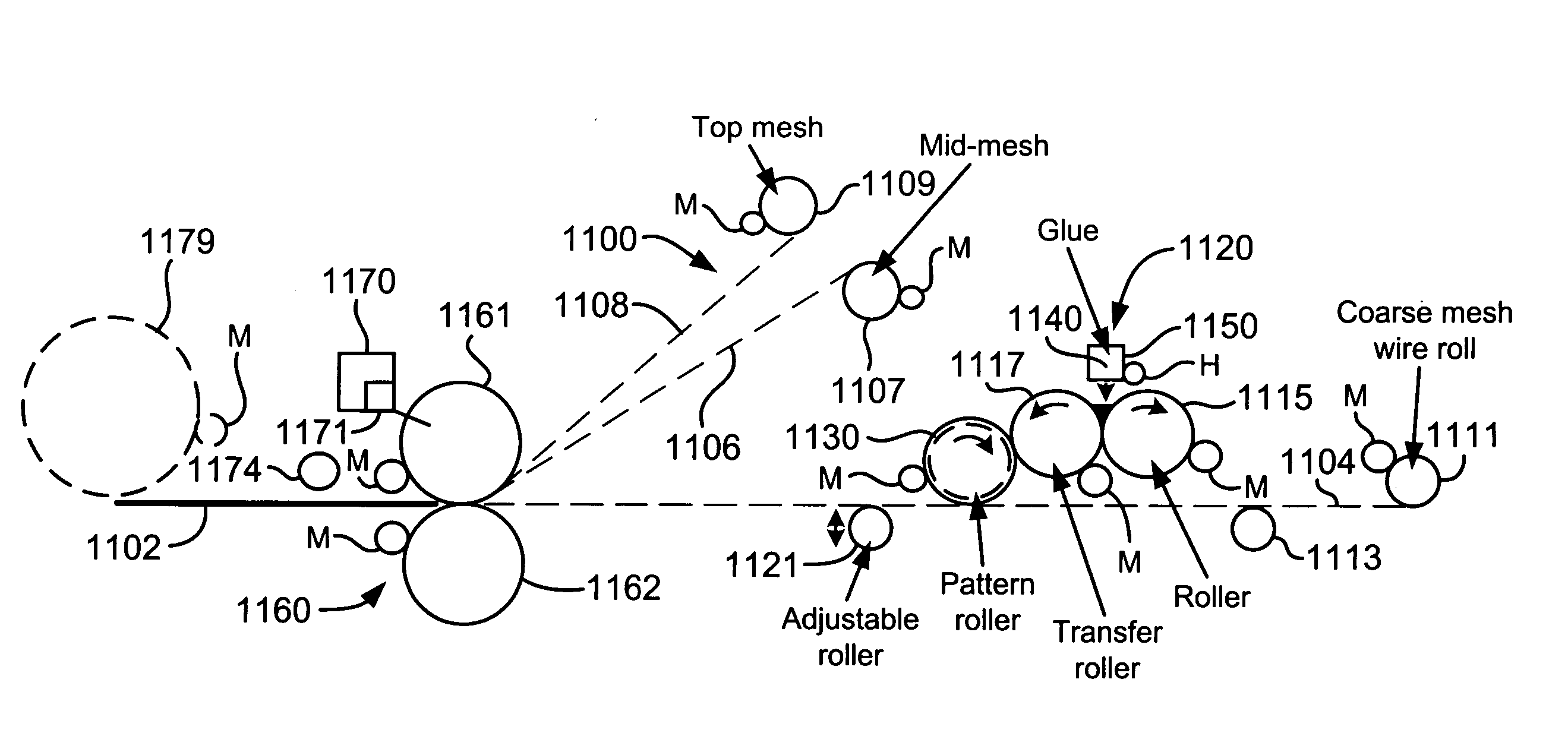
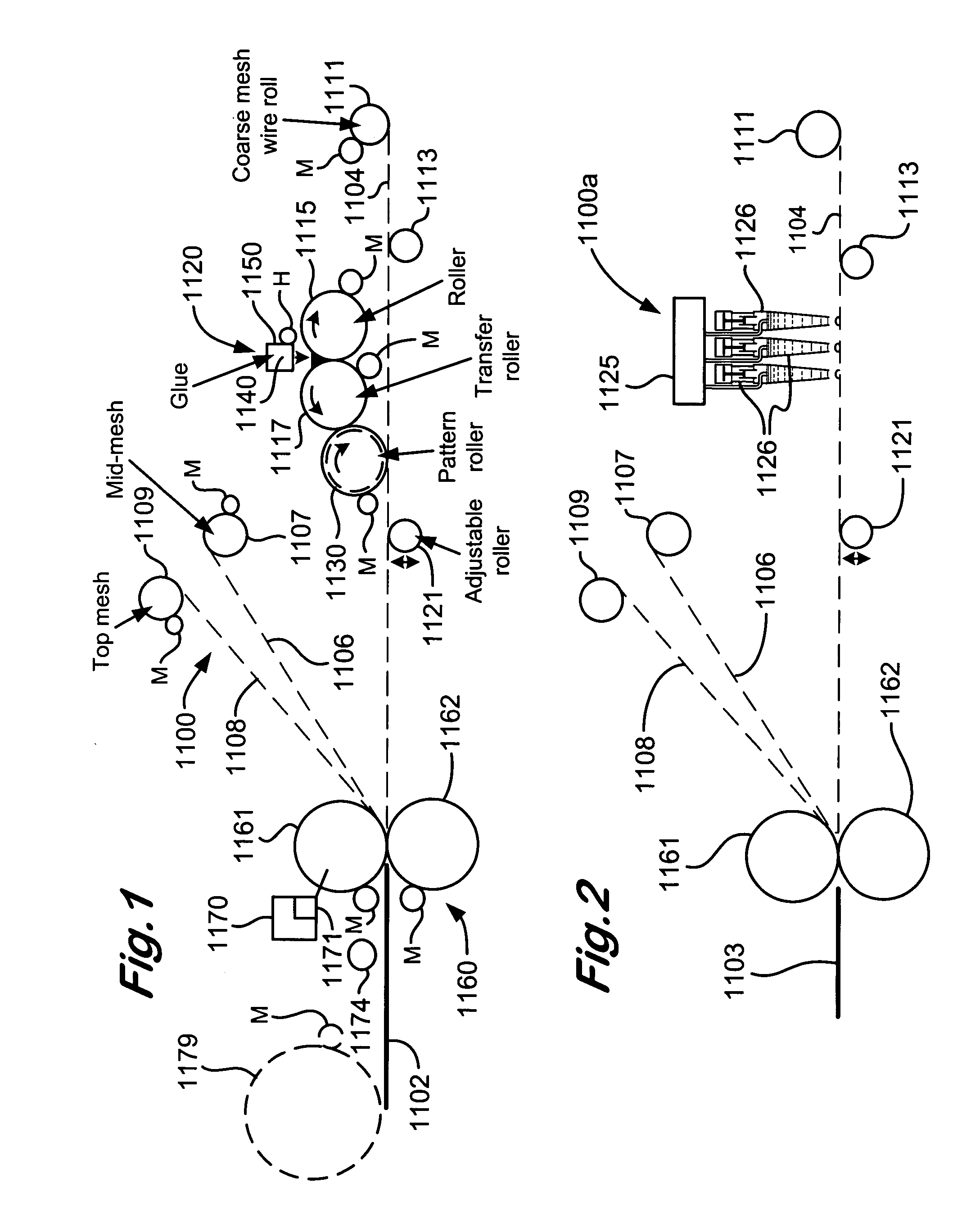
[0072] FIG. 1 shows a system 1100 according to the present invention for making a screen 1102 according to the present invention by a method according to the present invention. As shown the system 1100 produces a screen 1102 which includes a lower coarse mesh or screen 1004, an intermediate mesh or screen 1106, and a top mesh or screen 1108. Any one of these meshes (or screens) 1104, 1106, 1108 may be deleted. Alternatively one or more additional mesh layers may be added.

[0073] The coarse mesh 1104 is initially wound on a roller 1111 from which it is unwound and passes over a rotating roller 1113. From the roller 1113 the coarse mesh moves to a position beneath a gluing station 1120 where heated glue in a pattern is applied on the coarse mesh 1104. In one aspect the coarse mesh is 19 mesh made of wire with a diameter of about 0.126 inches. Of course any suitable mesh may be used. Sufficiently viscous hot melt glue is used which does not pass through and away from the mesh to which i...


PUM

PropertyMeasurementUnit
Forceaaaaaaaaaa

Abstract

Screen assemblies for a vibratory separator, and methods for making them, the method in one aspect including: applying glue in a glue pattern to at least one layer of screening material useful for screening fluid, said applying done by powered moving mechanical glue application apparatus; moving at least one glue dispensing manifold with a plurality of spaced-apart glue dispensing nozzles above the at least one layer of screening material to apply the glue pattern; combining the at least one layer of screening material to a second layer forming a screen combination; moving the screen combination apart from the powered moving mechanical glue application apparatus; and cutting part of the screen combination from the screen combination.

Description

[0001] This application is a continuation-in-part of U.S. application Ser. No. 10 / 087,025 filed Oct. 19, 2001 which is a continuation-in-part of U.S. application Ser. No. 09 / 603,531 filed Jun. 27, 2000 which is a continuation-in-part of U.S. application Ser. No. 09 / 517,212 filed Mar. 2, 2000 which is a continuation-in-part of U.S. application Ser. No. 09 / 454,722 filed on Dec. 4, 1999 which is a continuation-in-part of U.S. application Ser. No. 09 / 390,231 filed Sep. 3, 1999; and this application is a continuation-in-part of U.S. application Ser. No. 09 / 707,277 filed Nov. 6, 2000 which is a continuation-in-part of U.S. application Ser. No. 09 / 183,004 filed Oct. 30, 1998 issued as U.S. Pat. No. 6,186,337 on Feb. 13, 2001--all of which applications and patents are incorporated herein in their entirety for all purposes and with respect to all of which the present invention claims priority under the Patent Laws. This application is a continuation-in-part of U.S. application Ser. No. 10 / 61...

Claims


Application Information

Patent Timeline
IPC IPC(8): B01D29/01B01D33/00B01D33/03B07B1/00B07B1/46B07B1/48B07B1/49B21F27/00B32B3/24
CPCB01D29/012B01D33/0093B01D33/0384B01D2201/188B01D2201/52B07B1/00B07B1/4609B07B1/4618B07B1/4663B07B1/48B07B1/49B21F27/005B32B3/266B32B37/1292B32B2305/38B01D33/0376B01D29/05B01D29/72B01D29/07B01D33/0346B01D33/41B07B2201/02
Inventor ADAMS, THOMAS C.WARD, KERRYSEYFFERT, KENNETH W.SCHULTE, DAVID L. JR.LARGENT, DAVID W.GRICHAR, CHARLES N.MCCLUNG, GUY L. III
Owner VARCO I P INC
Why Eureka
Eureka Blog
Learn More