Spool brake device for dual-bearing reel

Active Publication Date: 2017-07-27
SHIMANO INC
View PDF0 Cites 3 Cited by
  • Summary
  • Abstract
  • Description
  • Claims
  • Application Information

AI Technical Summary

Benefits of technology

[0007]According to the spool brake device, the water landing determiner determines whether or not the terminal tackle has landed on water based on the output from the rotation detector after a casting, and determines that the terminal tackle has landed on water, for instance, when the rotational velocity of the spool becomes slow. When the water landing determiner determines that the terminal tackle has landed on water, the spool controller controls the spool brake such that the braking force is maintained at a magnitude at this point of time. When the water landing determiner herein determines that the terminal tackle has landed on water, the braking force is maintained at a magnitude at this point of time. Hence, the braking force becomes unlikely to vary during a water landing of the terminal tackle. Accordingly, a negative impact on a user is prevented.
[0008]The spool brake device for a dual-bearing reel can further include a rotational velocity calculator that calculates a rotational velocity of the spool based on the rotation of the spool detected by the rotation detector. The water landing determiner can determine that the terminal tackle has landed on water when the calculated rotational velocity is less than or equal to a predetermined value. According to this construction, a water landing of the terminal tackle can be determined based on a gradual reduction of the rotational velocity. Hence, it is possible to simplify an algorithm for determining a water landing of the terminal tackle.
[0009]When the rot

Problems solved by technology

Therefore, a big difference occurs in the magnitude of a braking force be

Method used


Image

  • Spool brake device for dual-bearing reel
  • Spool brake device for dual-bearing reel
  • Spool brake device for dual-bearing reel

Examples


Example

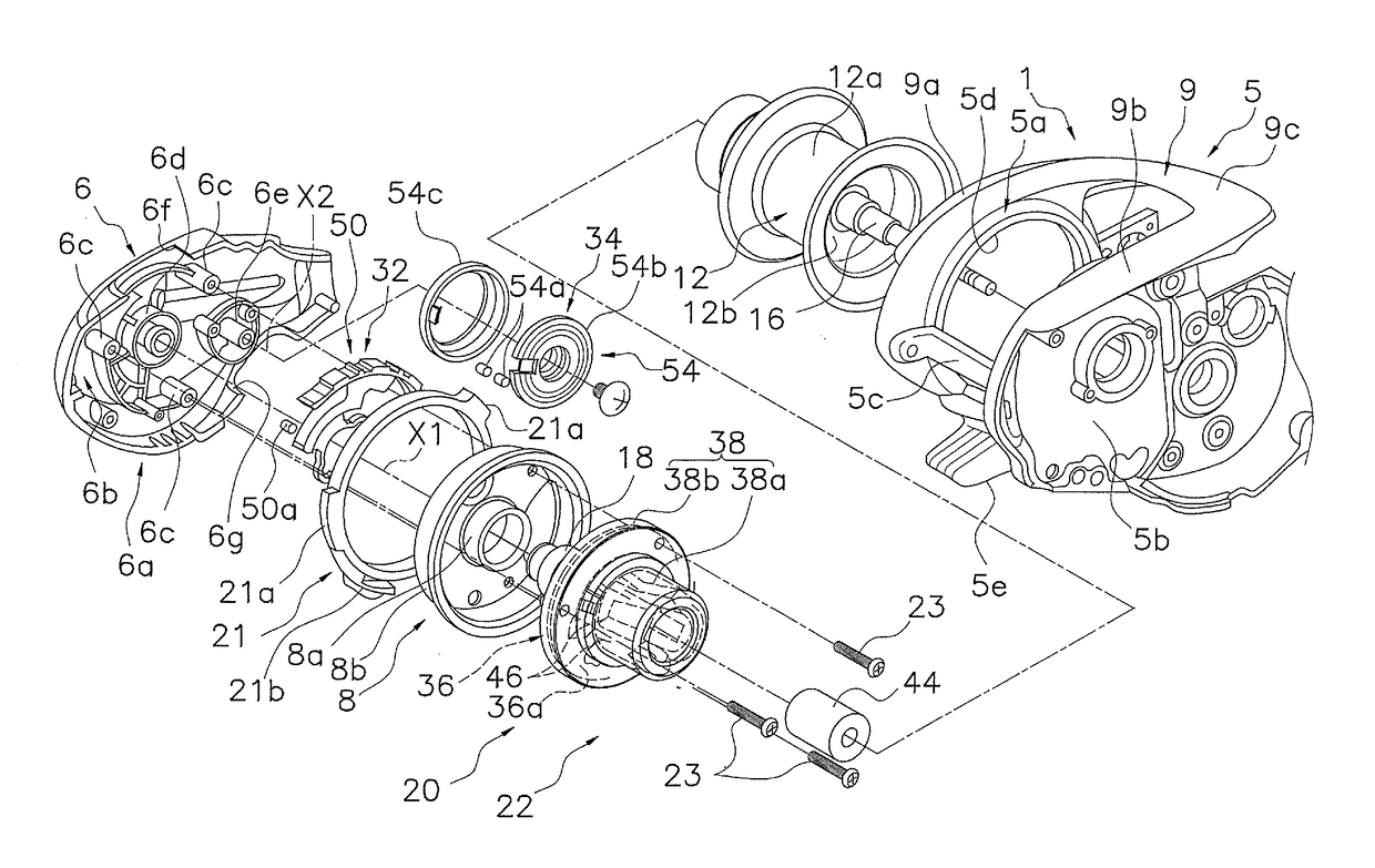
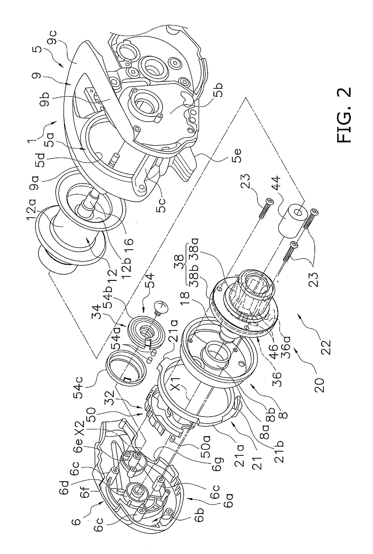
[0023]As shown in FIGS. 1 and 2, a dual-bearing reel 100 employing a preferred embodiment of the present disclosure includes a reel unit 1, a handle 2, a spool 12 and a spool brake mechanism 20 (see FIG. 2) to electrically brake the spool 12. The spool brake mechanism 20 is an exemplary spool brake device for the dual-bearing reel 100.

[0024]The reel unit 1 includes a frame 5, a first side cover 6 and a second side cover 7. The frame 5 is an integrally formed component. The first side cover 6 is disposed laterally to the frame 5 on the opposite side of the handle 2. The second side cover 7 is disposed laterally to the frame 5 on the same side as the handle 2.

[0025]As shown in FIG. 2, the frame 5 includes a first side plate 5a, a second side plate 5b, a plurality of coupling portions 5c and a thumb rest 9. The first side plate 5a is disposed on the opposite side of the handle 2. The second side plate 5b is opposed to the first side plate 5a. The coupling portions 5c couple the first s...


PUM


Abstract

A spool brake device for a dual-bearing reel, the spool brake device includes a spool brake, a rotation detector, and a spool controller. The spool brake can electrically brake a spool during a releasing of a fishing line by applying a braking force to the spool. The rotation detector can electrically detect a rotation of the spool. The spool controller can determine whether a terminal tackle has landed on water based on an output from the rotation detector after a starting of a casting, and can control the spool brake such that the braking force is maintained at a magnitude when a determination that the terminal tackle has landed on water, the magnitude equal to a magnitude of the braking force at a point of time the determination is made that the terminal tackle has landed on water.

Description

CROSS-REFERENCE TO RELATED APPLICATIONS[0001]This application claims priority to Japanese Patent Application No. 2016-010627 filed on Jan. 22, 2016, the entirety of which is hereby incorporated by reference in its entirety.BACKGROUNDp Technical Field[0002]The present disclosure relates to a spool brake device, and particularly to a spool brake device for a dual-bearing reel, which is electrically controllable.Background Information[0003]There has been known so far a type of dual-bearing reel in which a spool is electrically controllable (see Japan Laid-open Patent Application Publication No. 2014-82937). In the well-known type of dual-bearing reel, a spool brake device includes a magnet, coils and a control device. The magnet is unitarily rotatable with the spool. The coils are mounted to a reel unit and are opposed to the magnet. The control device adjusts a braking force by performing PWM (Pulse Width Modulation) for electric current flowing through the coils. The control device c...

Claims


Application Information

Patent Timeline
IPC IPC(8): A01K89/0155
CPCA01K89/0155A01K89/033A01K89/01555A01K89/045A01K89/01931
Inventor ISHIKAWA, YUICHIRONIITSUMA, AKIRA
Owner SHIMANO INC
Why Eureka
Try Eureka