Cleaning blade

a blade and blade body technology, applied in the field of cleaning blades, can solve the problems of short contact pressure, curving of the front end of the blade, and toner slipping through, etc., and achieve the effects of enhancing the rigidity of the blade part, and increasing the contact pressure of the blade par

Inactive Publication Date: 2017-08-03
SUMITOMO RIKO CO LTD
View PDF3 Cites 0 Cited by
  • Summary
  • Abstract
  • Description
  • Claims
  • Application Information

AI Technical Summary

Benefits of technology

[0011]In consideration of such a background as described above, the present disclosure provides a cleaning blade that is capable of preventing or reducing slip-through of a toner in a long time use by increasing a contact pressure without changing the position of the cleaning blade to be closer to the a counterpart member, and also by ensuring sufficient followability to the surface of the counterpart member.
[0013]The above described cleaning blade has the blade part that is joined to the plate-shaped portion of the support in integral forming. Because the blade part has the reinforcing portion in addition to the blade body portion, the thickness (cross sectional area) of the blade part increases on the base end side so as to enhance the rigidity of the blade part. Thus, according to this cleaning blade, the contact pressure of the blade part can be increased without changing the position of the cleaning blade to be closer to the counterpart member.
[0014]Furthermore, the reinforcing portion extends from the surface of the blade body portion, and is formed integrally with the blade body portion. In addition, the reinforcing portion has, on the outer surface, a curved surface that curves inward, and thus the curved surface smoothly shifts to the surface of the blade body portion at the front end edge of the reinforcing portion. The reinforcing portion can disperse a stress in a whole body, so that the stress is less likely concentrated on the front end edge of the reinforcing portion. Consequently, the blade body portion is hardly bent at a position of the front end edge of the reinforcing portion in sliding contact with the counterpart member, so that the contact angle can be easily maintained to be large. In this way, the cleaning blade can secure sufficient followability to the surface of the counterpart member.
[0015]As mentioned above, the cleaning blade can prevent or reduce the slip-through of a toner in a long time use by increasing the contact pressure without changing the position of the cleaning blade to be closer to the counterpart member, and also by securing sufficient followability to the surface of the counterpart member.

Problems solved by technology

Thus, if a conventional cleaning blade as widely known is used under the condition that a contact pressure to press the surface of the counterpart member is set at the same level as conventional, slip-through of a toner is caused by shortage of the contact pressure.
Under such a background, even a slight clearance between the surface of the counterpart member and the edge portion of the blade portion may cause the toner to slip therethrough.
This solution, however, increases a frictional force between the blade part and the counterpart member, which causes curling up of the front end of the blade part.
If cleaning is continuously performed under such a condition that the blade part is curled up, the side face of the blade part suffers abrasion in some places.
Progressed abrasion, in some cases, may chip the front end of the blade part.
As mentioned above, this solution cannot address a recent requirement for enhancement of durability of the image forming device.
However, because the cleaning blade is provided with reinforcing elastic bodies having a triangular shape or the like in cross section, on both of the plate surface of the blade part and the front end face of the supporting plate, the following problem arises.
In fact, according to this cleaning blade, the followability to the surface of the counterpart member lowers unintentionally by increasing the contact pressure without any consideration, so that slip-through of a toner generates in a long time use.

Method used


Image

  • Cleaning blade
  • Cleaning blade
  • Cleaning blade

Examples


embodiment 1

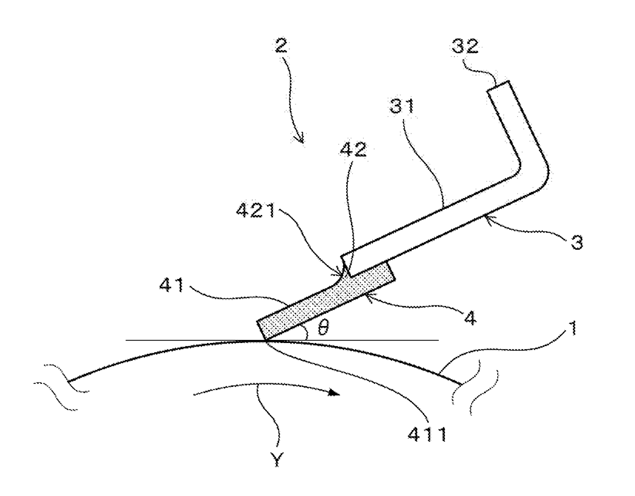
[0047]A cleaning blade according to Embodiment 1 will be described with reference to FIGS. 1 to 6. As illustrated in FIG. 1, a cleaning blade 2 of the present embodiment is used to remove residual toner (not shown) remaining on a surface of a counterpart member 1 in an electrophotographic image forming device by sliding contact with the counterpart member 1. In the present embodiment, the counterpart member 1 is a photoreceptor drum as an image bearing member. In the cleaning blade 2, a front edge portion 411 on the front end of the blade part 4 serves as a sliding contact portion to be brought in sliding contact with the counterpart member. In FIG. 1, θ represents an abutting angle, and an arrow Y shows a rotation direction of the photoreceptor drum as the image bearing member.

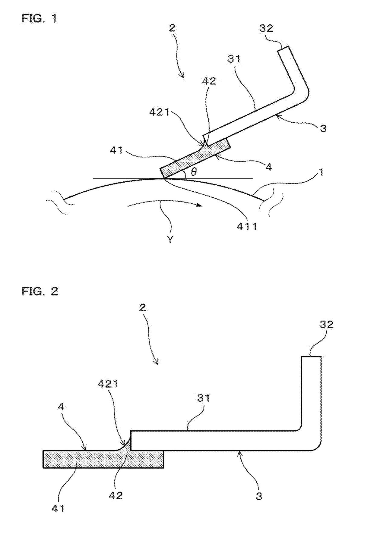
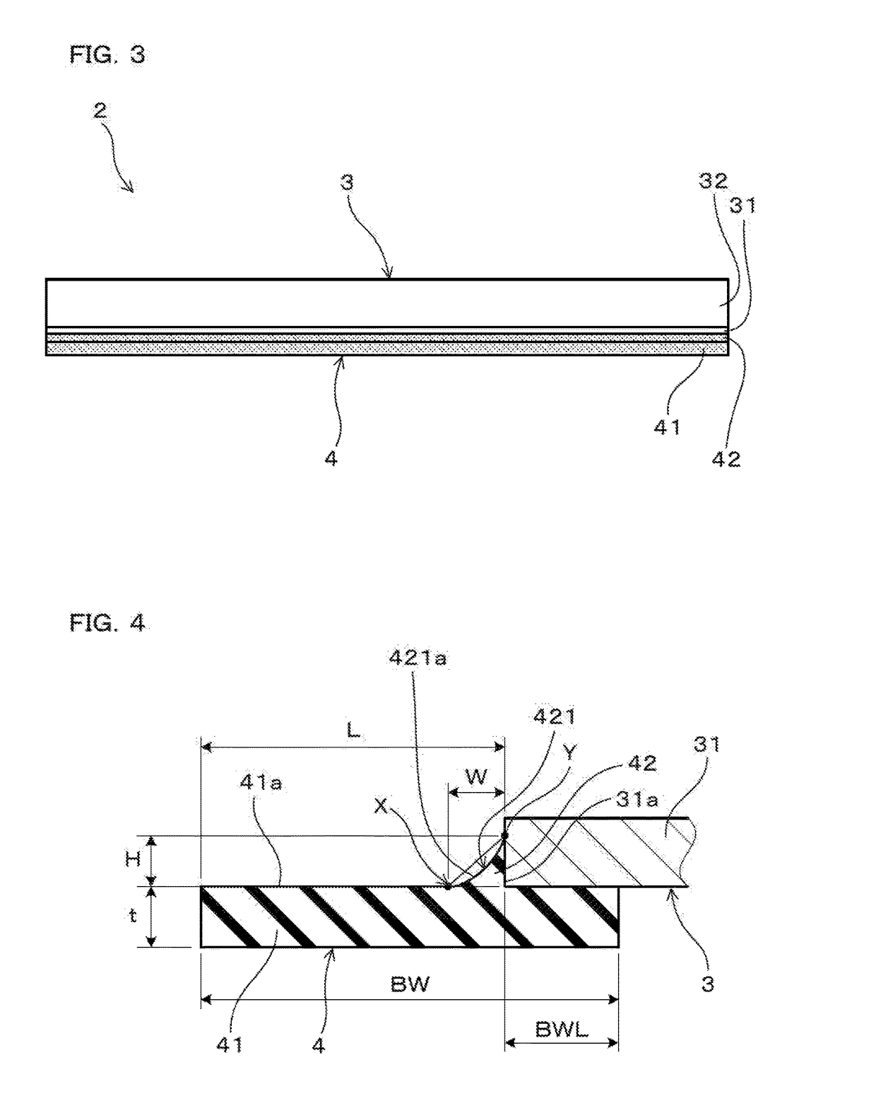
[0048]As shown in FIGS. 2 to 4, the cleaning blade 2 of the present embodiment includes a support 3 including a plate-shaped portion 31 and a blade part 4 made of polyurethane. The blade part 4 is joined to t...

embodiment 2

[0053]A cleaning blade according to Embodiment 2 will be described with reference to FIG. 7. As illustrated in FIG. 7, the cleaning blade 2 of the present embodiment has the blade body portion 41 that is joined to the plate surface of the plate-shaped portion 31 in an inclined manner with respect to the plate surface. The inclination is set in such a direction that the front end of the blade body portion 41 is apart from the counter member 1. The cleaning blade 2 in Embodiment 2 is one example applied to other model different from the electrophotographic image forming device employed in Embodiment 1. Other configurations are the same as those in Embodiment 1.

embodiment 3

[0054]A cleaning blade according to Embodiment 3 will be described with reference to FIG. 8. As illustrated in FIG. 8, the cleaning blade 2 of the present embodiment has the blade body portion 41 that is joined to the plate surface of the plate-shaped portion 31 in an inclined manner with respect to the plate surface. The inclination is set in such a direction that the front end of the blade body portion 41 approaches the counter member 1. The cleaning blade 2 of the present embodiment is one example applied to other model different from the electrophotographic image forming devices employed in Embodiments 1 and 2. Other configurations are the same as those in Embodiment 1.


PUM


Abstract

The present disclosure provides a cleaning blade (2) that prevents toner from slipping through the cleaning blade in a long time use. The cleaning blade (2) is used to remove residual toner remaining on a surface of a counterpart member (1) in an electrophotographic image forming device by sliding contact with the counterpart member (1). The cleaning blade (2) includes a support (3) including a plate-shaped portion (31); and a blade part (4) made of polyurethane, and joined to the plate-shaped portion (31) in integral forming. The blade part (4) includes a plate-shaped blade body portion (41) that is joined to a plate surface of the plate-shaped portion (31), and a reinforcing portion (42) that extends from a surface of the blade body portion (41) and is joined to a front end face of the plate-shaped portion (31). The reinforcing portion (42) has a curved surface (421) that curves inward.

Description

CROSS-REFERENCE[0001]This application is a Continuation of International Application No. PCT / JP2015 / 077646 filed Sep. 30, 2015, which claims priority to Japanese Patent Application No. 2014-258200 filed on Dec. 22, 2014. The entire contents of which are incorporated herein by reference.TECHNICAL FIELD[0002]The present disclosure relates to a cleaning blade, and more particularly to a cleaning blade for use in an electrophotographic image forming device.BACKGROUND ART[0003]An electrophotographic image forming device employs a cleaning blade to clean, for instance, the surfaces of an image bearing member such as a photoreceptor and an intermediate transfer belt. The cleaning blade has a blade part, a front edge portion of which is pressed onto the surfaces of the image bearing member and the intermediate transfer belt as counterpart members. A residual toner that remains on the surface of the counterpart members is scraped off and removed by sliding contact of the edge portion with th...

Claims


Application Information

Patent Timeline
Patent Type & Authority Applications(United States)
IPC IPC(8): G03G21/00
CPCG03G21/0017G03G21/0029
Inventor NAKAMURA, NAOKIYAMAGUCHI, KAZUSHISUZUKI, SATOSHINIMURA, YASUNORI
Owner SUMITOMO RIKO CO LTD
Why Eureka
Try Eureka