Restriction unit for adjustment of seat post

a technology for restricting units and seat posts, which is applied in the direction of cycle saddles, transportation and packaging, cycle equipment, etc., can solve the problems of long time spent by users to adjust seat posts, shorten travel distance, and conventional adjustment is obviously not efficient, and achieves the effect of convenient assembly and disassembly

Inactive Publication Date: 2017-08-10
KIND SHOCK HI-TECH CO LTD
View PDF0 Cites 0 Cited by
  • Summary
  • Abstract
  • Description
  • Claims
  • Application Information

AI Technical Summary

Benefits of technology

[0013]The primary object of the present invention is to provide a seat post adjustment device which has a restriction unit connected to the outer tube so as to restrict the travel distance of the inner tube relative to the outer tube. The adjustment of the inner tube is stage-less and the position of the seat can be micro-adjusted.
[0014]Another object of the present invention is to provide a seat post adjustment device wherein when the lower end of the inner tube contacts the restriction unit, the inner tube cannot be further lowered such that the minimum height of the seat above the outer tube is set.
[0015]Yet another object of the present invention is to provide a seat post adjustment device wherein the restriction unit is easily assembled and dis-assembled from the outer tube. When the restriction unit is removed, the original travels distance of the outer tube is retrieved.

Problems solved by technology

However, the travel distance of the seat post is set and cannot change, that is to say, the user cannot shorten the travel distance of the seat post or to restrict the range that the seat post moves.
Therefore, when adjusting the height of the seat, the user has to spend a long time to adjust the seat post relative to the seat tube by operating the locking unit between the seat post and the seat tube.
The seat should be lowered before carrying the bicycles to trains or public transportation vehicles, the conventional adjustment is obviously not efficient and convent to the users.
Nevertheless, all of the conventional adjustment devices known to applicant can only adjust the seat post within a limit range, and the seat post can only be positioned at the position where there is the hole or the notch located.
The adjustment cannot meet all of the users' needs.
Besides, the engagement between the stop member or the protrusion with the hole or notch cannot be cooperated with the adjustment device using pneumatic cylinder or hydraulic cylinder.

Method used


Image

  • Restriction unit for adjustment of seat post
  • Restriction unit for adjustment of seat post
  • Restriction unit for adjustment of seat post

Examples


second embodiment

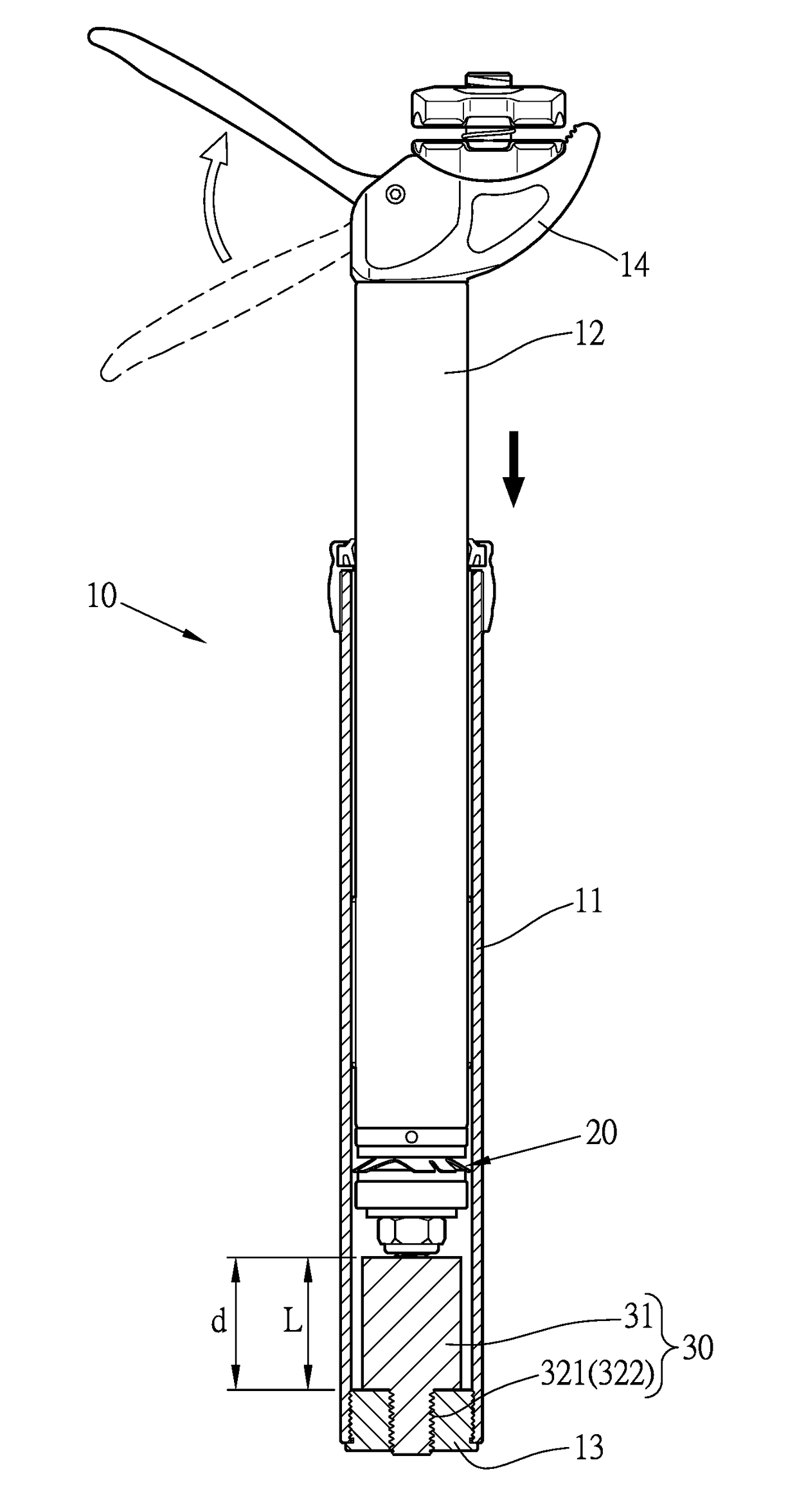
[0048]FIGS. 5 to 7 show the present invention, wherein the adjustment unit 20 has a rod 21 located in the travel distance “d”. The rod 21 has a first end thereof extending beyond the adjustment unit 20 and through the restriction member 31. The first end of the rod 21 is connected to the end member 13. The restriction member 31 is securely mounted to outside of the rod 21. This embodiment is used for the adjustment device whose travel distance “d” having the rod 21. The restriction member 31 has a certain thickness and is tightly mounted to the rod 21 at the position where the length “L” is from the end member 13 to the restriction member 31. When adjusting the inner tube 12, the adjustment unit 20 and the inner tube 12 both move toward the interior of the inner tube 11 until the adjustment unit 20 contacts the restriction member 31.

[0049]The embodiment provides another type of the restriction unit 30, and the restriction member 31 is located between two ends of the travel distance ...

third embodiment

[0050]FIGS. 8 to 10 show the present invention, wherein the adjustment unit 20 has the rod 21 which extends beyond the adjustment unit 20. The exposed portion of the rod 21 extends through the restriction member 31 and is fixed to the end member 13. The restriction member 31 is tightly mounted to the rod 21. The restriction member 31 has a passage 311 defined centrally therethrough, and the restriction member 31 has a slot 312 defined radially therethrough. The slot 312 communicates with the passage 311. The rod 21 is engaged with the passage 311 via the slot 312 from radial direction. Multiple protrusions 313 extend radially from the inner periphery of the restriction member 31 and the protrusions 313 securely contact against the outside of the rod 21. The restriction member 31 has scales 314 marked on the outside thereof and the scales 314 are provided for reference when the restriction member 31 is to be cut.

[0051]The embodiment is used for the type of adjustment wherein the end ...

fourth embodiment

[0053]FIGS. 11 to 12 show the fourth embodiment, wherein the restriction member 31 is located in the travel distance “d” in the outer tube 11. The restriction member 31 has a slot 312 defined radially therethrough and the slot 312 communicates with the passage 311. The restriction member 31 is mounted to the rod 21, and the outer periphery of the restriction member 31 is tightly engaged with the inner periphery of the outer tube 11.

[0054]The embodiment discloses that the restriction member 31 has a certain thickness and has the slot 312. The restriction member 31 is tightly engaged with the inner periphery of the outer tube 11 at the desired length “L”. The restriction member 31 is located between two ends of the travel distance “d”.


PUM


Abstract

A seat post adjustment device includes an outer tube and an inner tube which has the first end thereof inserted into the outer tube, and a seat is connected to the second end of the inner tube. An adjustment unit is connected to the inner tube, the adjustment unit and the inner tube are linearly movable for a travel distance in the outer tube. An end member is connected to the lower end of the outer tube. A restriction unit is located in the outer tube and has a restriction member which has a length and can be cut when needed such that the travel distance of the inner tube in the outer tube is restricted when the adjustment unit contacts the restriction member.When the adjustment unit contacts the restriction member, the minimum height of the second end of the post beyond the outer tube is set.

Description

BACKGROUND OF THE INVENTION[0001]1. Fields of the invention[0002]The present invention relates to a seat post adjustment device, and more particularly, to a restriction unit for restricting the travel distance of the seat post in the seat tube.2. Descriptions of Related Art[0003]The conventional bicycle seat is connected to the top of the seat post which is movably inserted in the seat tube. The height of the seat is adjustable to meet the requirements of different users.[0004]One of the conventional adjustment device uses hydraulic liquid to linearly move the seat post in the seat tube and to maintain the position of the seat post relative to the seat tube. Another conventional adjustment device uses the combination of pneumatic and hydraulic mechanism to linearly move the seat post in the seat tube and to maintain the position of the seat post relative to the seat tube. Yet another conventional adjustment device uses mechanical method to achieve the above mentioned purposes.[0005]...

Claims


Application Information

Patent Timeline
Patent Type & Authority Applications(United States)
IPC IPC(8): B62J1/08
CPCB62J2001/085B62J1/08
Inventor HSU, JUNG YU
Owner KIND SHOCK HI-TECH CO LTD
Why Eureka
Try Eureka