Level Control System for a Liquid Filled Basin

a level control system and liquid filling technology, applied in the direction of level control, sewer system, construction, etc., can solve the problem of the gate flap being initially opened, and achieve the effect of less closing moment, less closure force, and reduced opening force on the ga

Pending Publication Date: 2022-03-10
OVIVO INC
View PDF12 Cites 0 Cited by
  • Summary
  • Abstract
  • Description
  • Claims
  • Application Information

AI Technical Summary

Benefits of technology

[0004]The current invention is a mechanical liquid level control system configured such that regardless of changes in the flow rate into and from the basin, even sudden surges of flow, the liquid level can be controlled and managed within a set of desired parameters. In the system is an intermediate headloss device, which can be, for example, a submerged effluent launder in a clarifier of a sewage treatment plant, withdrawing liquid from below the surface. A flap gate is positioned downstream of the submerged effluent launder or other headloss device. The closing force on the flap gate, which is on a horizontal hinge axis, is exerted by the weight of the flap itself and by a counterweight or counterforce attached to control the flap gate opening and closing, so that a controlled outflow of water is maintained under all conditions, preventing flushing or surging of water out of the basin or vessel. Unlike embodiments described in application Ser. No. 17 / 280,771, additional embodiments of the current invention do not employ a float or other mechanical device directly responsive to the change of liquid level in the basin. Still the invention can maintain a minimal, acceptable range of liquid level variation, the level variation depending on basin inflow variations.
[0006]As the liquid level in the tank or basin decreases due to reduced inflow to the basin, the chamber level will also fall initially because the gate is open, and hydraulic head acting on the headloss device has lessened. The reduced chamber head (which lessens the gate opening force) will allow the gate to begin moving toward closure thereby causing the counterweight to increase in applied closure moment, and the head in the intermediate device increases (headloss decreases). The gate continues to move toward closure. If a substantially constant inflow of liquid to the basin occurs for a time, the gate can find equilibrium at a partially open position and the basin liquid will be slightly above design level.
[0007]The system typically will prevent flushing or undulation through the gate, wherein liquid flow drops quickly in the intermediate zone, the gate drops to nearly closed, the liquid rises again quickly in the intermediate zone, quickly opening the flap and flushing, and so on. An optional dampening device can be included to assure this does not occur. In addition, the travel distance of the counterweight, and thus of the gate flap, can be limited, so that a maximum opening of the gate is defined.

Problems solved by technology

Sufficient head in a chamber of the intermediate headloss device, caused by a rise in the liquid level in the main basin, will cause the gate flap to initially open.
The counterweight can travel to a position almost vertically above the gate hinge, at which point it has neither an opening nor a closing effect (any further weight movement would tend to slightly assist opening of the gate, which is undesirable in most cases).

Method used


Image

  • Level Control System for a Liquid Filled Basin
  • Level Control System for a Liquid Filled Basin
  • Level Control System for a Liquid Filled Basin

Examples


Embodiment Construction

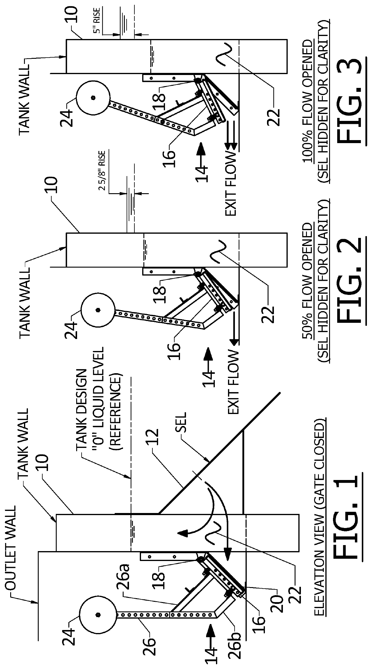
[0017]In the drawings FIG. 1 shows the tank or basin liquid level at design level, noted as zero. The basin wall is shown at 10. A submerged effluent launder (SEL) is indicated at 12, which can be similar to that shown in U.S. Pat. No. 9,919,244, withdrawing basin liquid from below the surface via a multiplicity of small openings. The SEL 12 is shown in FIG. 1 (but not in FIGS. 2 and 3, for clarity), and liquid is nearly always flowing into the SEL. The SEL is a headloss inducing device, in that it has submerged apertures that can only receive liquid at a limited rate. The SEL acts as a “choke” on the flow out of the tank. Higher head directly upstream of the SEL will naturally increase flow into the SEL, and vice versa but to a limited extent.

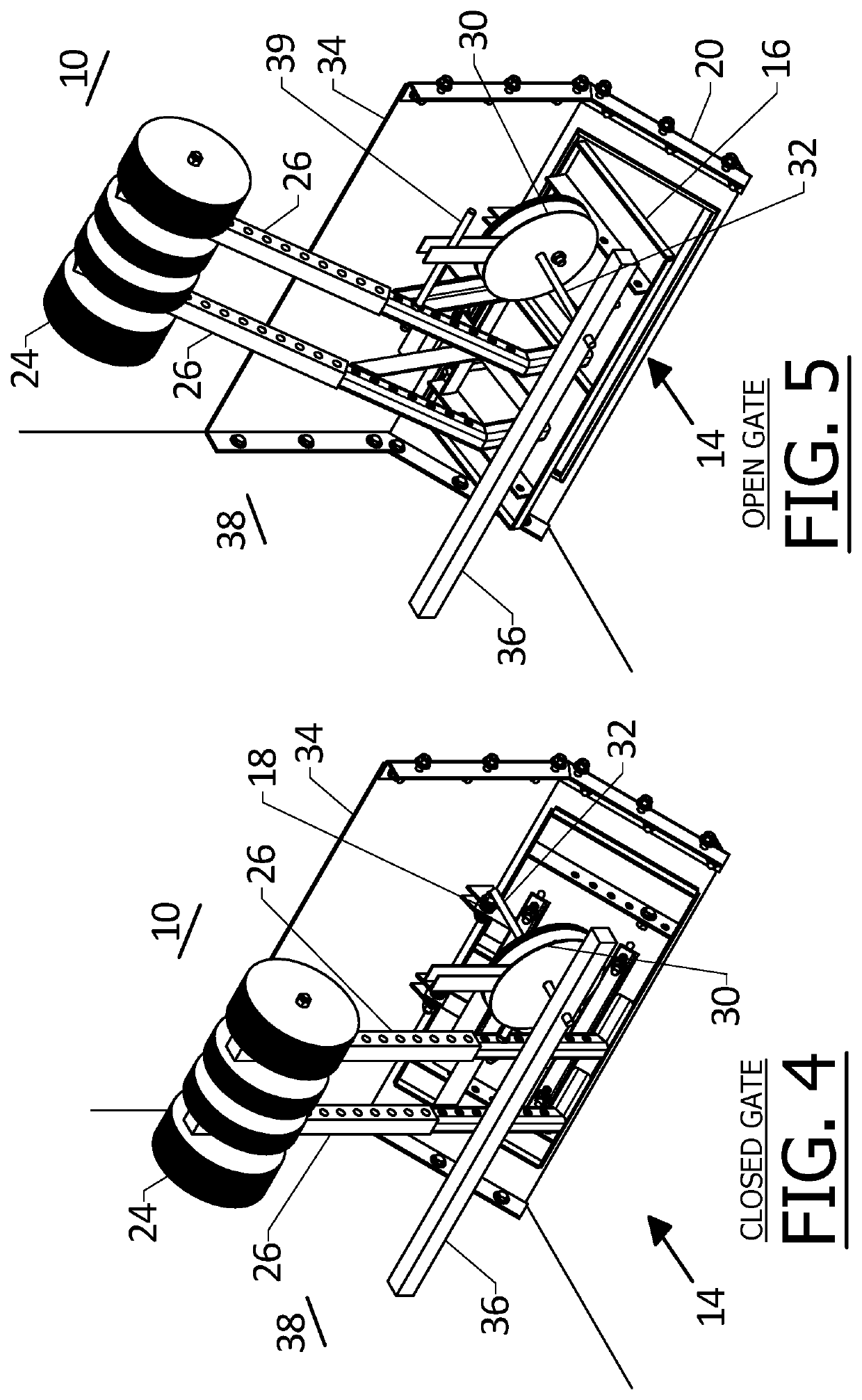
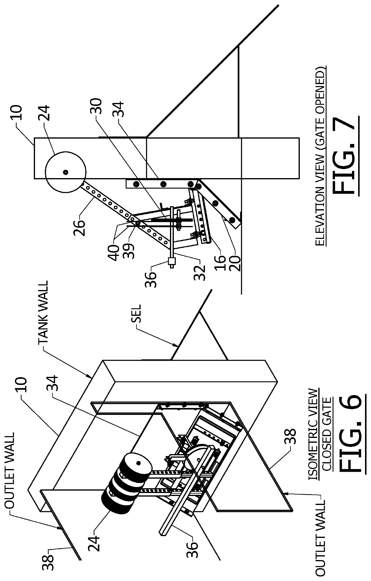
[0018]Liquid collected in the SEL flows to a flap gate 14 that has a gate flap 16 hinged at 18 to fixed structure on the wall 10 and which closes against a valve closure seat 20. In FIGS. 1 to 3 an intermediate chamber 22 is shown between the ...


PUM


Abstract

A liquid level control system employs a flap gate for discharging liquid, but with a midstream headloss inducing device between the basin or tank and the flap gate. The flap gate opens when liquid level in the basin rises, and the opening of the gate is controlled by a counterweight positioned so as to decrease closing force as the gate opens farther, thus managing the outflow of liquid to efficiently return the basin to a design level. If flow from the basin is generally constant, the system will reach a point of equilibrium of gate opening and closing forces while liquid flows out from the basin.

Description

[0001]This application is a continuation-in-part of application Ser. No. 17 / 280,771, filed Mar. 26, 2021, which claimed benefit of provisional application Ser. No. 62 / 738,974, filed Sep. 28, 2018 and 62 / 757,459, filed Nov. 8, 2018, as well as international application No. PCT / US2019 / 053677, published as WO / 2020 / 069457, filed Sep. 27, 2019. The disclosure of publication No. WO / 2020 / 069457 is incorporated herein by reference as to the specific embodiments there described, some of which include a basin level-responsive actuator as a part of gate control.BACKGROUND OF THE INVENTION[0002]This invention concerns control of liquid level in a basin or tank, by controlling flow out from the basin. In one application the basin or vessel is a clarifier in a sewage treatment plant.[0003]In absence of an overflow weir, a midstream device is needed to equally distribute flow from a clarifier. The problem with conventional liquid level control systems today is that they cannot efficiently handle n...

Claims


Application Information

Patent Timeline
Patent Type & Authority Applications(United States)
IPC IPC(8): G05D9/02
CPCG05D9/02E03F5/107
Inventor BEAMAN, TYSONBEAMAN, GARRETVORWALLER, JOHN
Owner OVIVO INC
Why Eureka
Try Eureka