Remote-control system with homopolar magnets

a technology of homopolar magnets and remote control systems, applied in the direction of mechanical control devices, instruments, pulse techniques, etc., can solve the problems of loss of reset effect, assembly space needs to be increased in an unacceptable way, and the reset effect is not effective over an arbitrarily large travel distance, so as to save assembly space, weight and cost

Active Publication Date: 2021-03-30
FM MARKETING
View PDF5 Cites 0 Cited by
  • Summary
  • Abstract
  • Description
  • Claims
  • Application Information

AI Technical Summary

Benefits of technology

[0006]Here, the said remote-control system offers a solution by arranging the armature magnet and the sensor magnet in a homopolar position from the beginning, and having them move towards each other homopolarly. This causes both magnets to constantly repel each other, thus avoiding a transition between an opposite and a homopolar arrangement of both magnets, thereby limiting the travel distance of the pushbutton only by the magnetic force of the two magnets and the weight force of the pushbutton including the sensor magnet. The arrangement of the abovementioned remote-control system, however, is also subject to this limitation.
[0021]In an additional embodiment of the said remote-control system, the armature magnet is aligned in a line with the sensor magnet when viewed in the pressure application direction, wherein another armature magnet is fixed on the housing which is located in a line with the further sensor magnet when viewed in the pressure application direction. In this way, both armature magnets may be executed on a small geometric scale, which leads to savings in assembly space, weight and costs.

Problems solved by technology

When viewed in the pressure application direction, such reset effect, however, is not effective over an arbitrarily large travel distance of the pushbutton, because if the spherical sensor magnet is pushed too far out of the circular armature magnet, both magnets will be arranged in homopolar position, and the circular armature magnet repels the spherical sensor magnet.
This would lead to a loss of the reset effect.
The travel distance could be extended by selecting bigger magnets, but then the assembly space would have to be increased in an unacceptable way.
As remote-control systems are mass-produced goods, the costs for correspondingly bigger magnets would also increase in an unacceptable way.
The arrangement of the abovementioned remote-control system, however, is also subject to this limitation.

Method used


Image

  • Remote-control system with homopolar magnets
  • Remote-control system with homopolar magnets
  • Remote-control system with homopolar magnets

Examples


Embodiment Construction

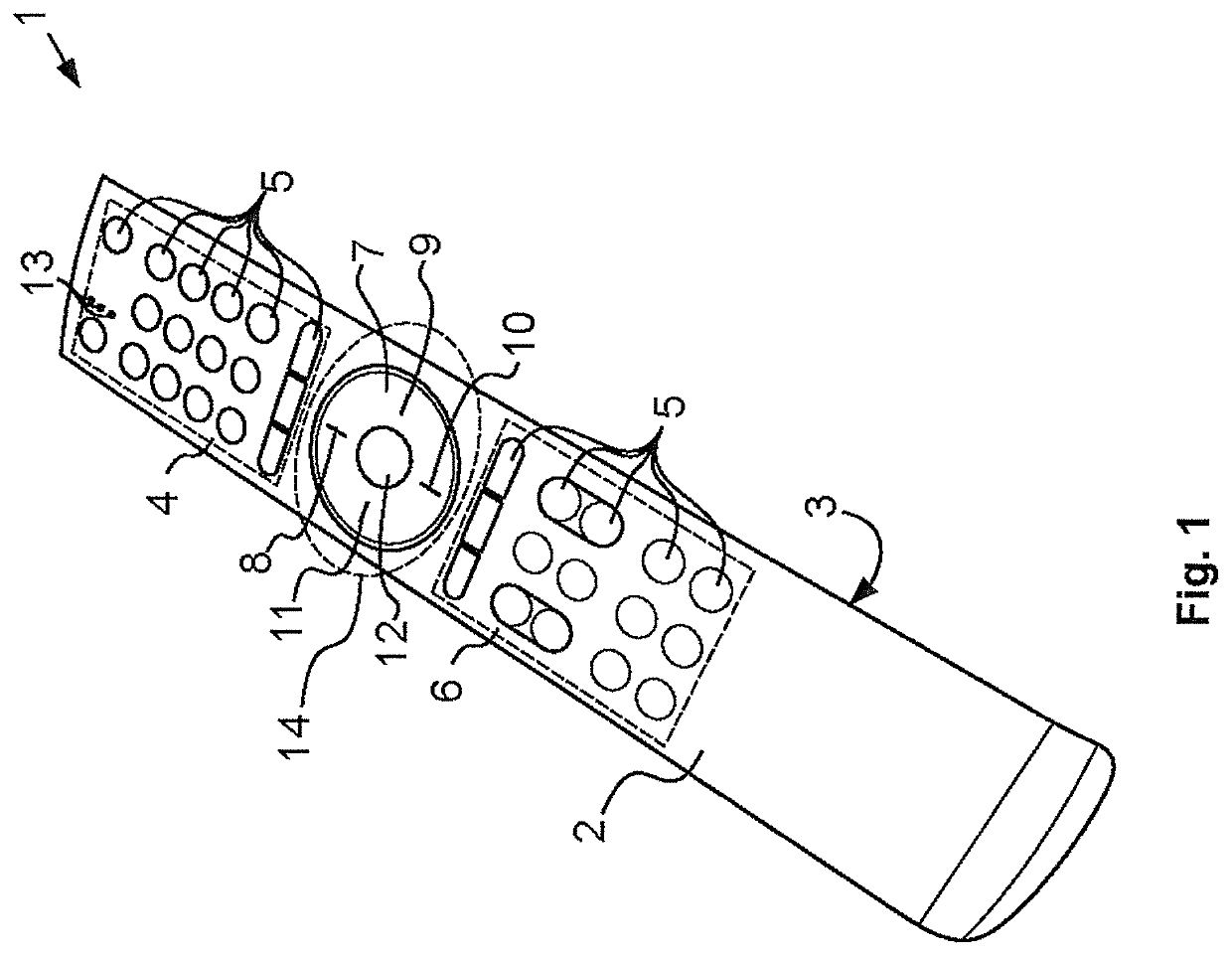
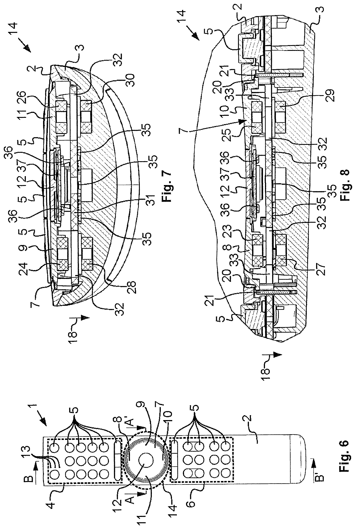
[0036]The remote-control system 1 comprises a housing comprising an upper casing 2 and a lower casing 3, as well as a first keypad 4 with a plurality of pushbuttons 5 and a second keypad 6 with a plurality of pushbuttons 5. For reasons of clarity, not all of the pushbuttons 5 in the keypads 4, 6 are marked with reference signs in the figures.

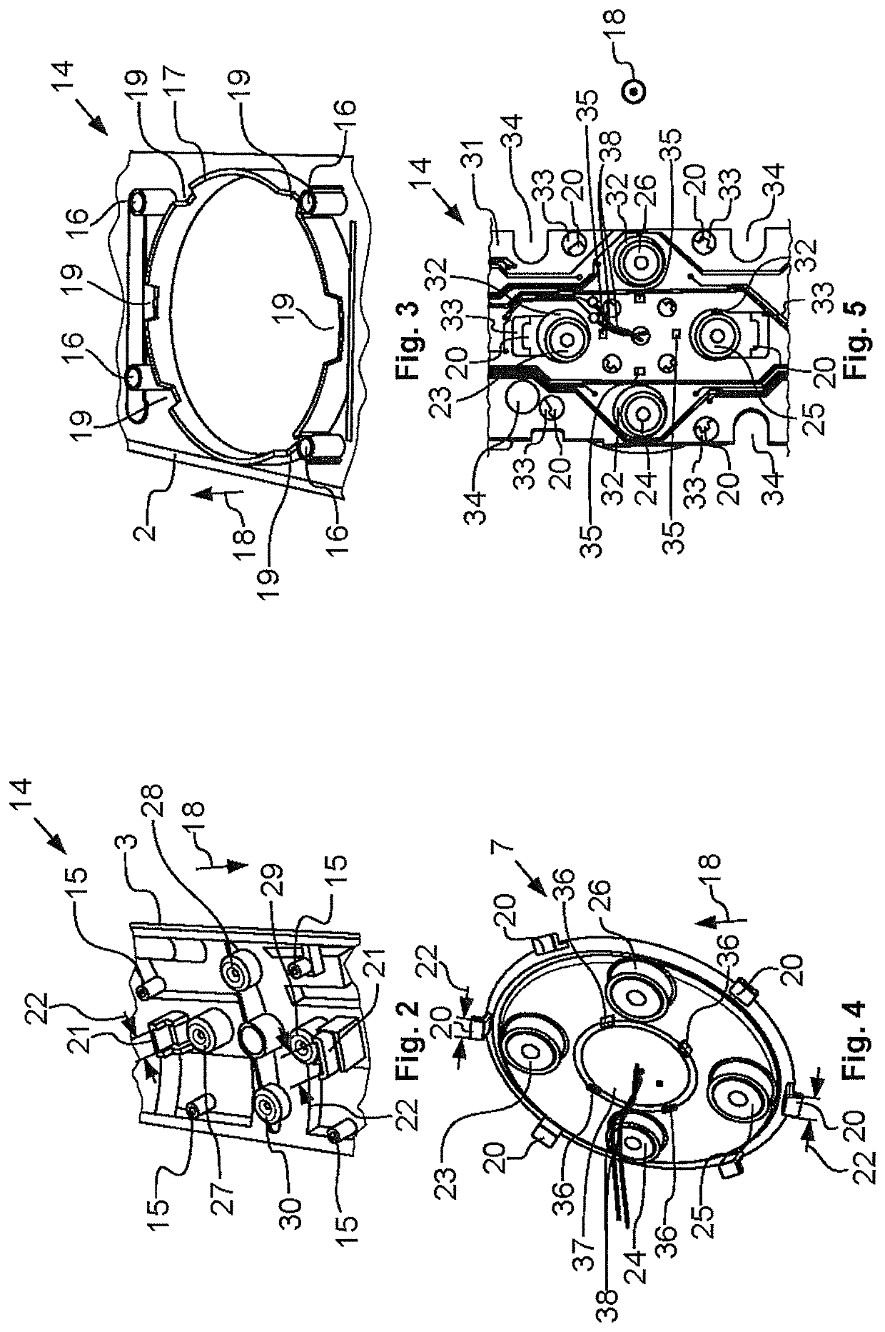
[0037]Both keypads 4 and 6 are separated from one another by a control ring 7 comprising a first pushbutton 8, a second pushbutton 9, a third pushbutton 10 and a fourth pushbutton 11. The four pushbuttons are intended to move a control element on a multi-media system which is not shown, and are thus arranged in the four possible directions of movement and at a distance of 90° around a confirmation button 12.

[0038]The remote-control system 1 may be provided with other display elements 13, such as small lights, which can be used to display the functional condition of the remote-control system 1 to the user of the remote-control system 1.

[0039]The ...


PUM


Abstract

The invention relates to a remote-control system (1) comprising: a pushbutton (8) that can be pressed by a user for inputting information in that the user applies a pressure in a direction (18); a sensor magnet (23) arranged on the underside of the pushbutton (8), when viewed in the pressure application direction (18); and an armature magnet (27) arranged below the pushbutton (8), when viewed in the pressure application direction (18), and fixed relative to the pushbutton (8), wherein the magnetic poles (39, 41) of the sensor magnet (23) and of the armature magnet (27) are arranged in such a way that the pushbutton (8) is pressed by the sensor magnet (23) away from the armature magnet (27), against the pressure application direction (18).

Description

REFERENCE TO RELATED APPLICATIONS[0001]The present invention relates to a remote-control system. This application is a U.S. national stage application of International Patent Application No. PCT / EP2016 / 077282, filed Nov. 10, 2016, and claims the benefit of priority of German Application No. 10 2015 119 485.6, filed Nov. 11, 2015, the entire disclosures of which are incorporated herein by reference.FIELD OF THE INVENTION[0002]The present invention relates to a remote-control system.BACKGROUND[0003]A remote-control system is known, for example, from WO 2010 / 119 348 A1. It comprises a pushbutton to input information in that the user applies a pressure in a pressure application direction; a spherical sensor magnet arranged on the underside of the pushbutton, when viewed in the pressure application direction; and a circular armature magnet fixed relative to the pushbutton on the housing. The magnetic poles of the spherical sensor magnet and the circular armature magnet are arranged as op...

Claims


Application Information

Patent Timeline
Patent Type & Authority Patents(United States)
IPC IPC(8): H03K17/97G05G1/02G05G5/05H01H36/00G05G9/047
CPCH03K17/97G05G1/02G05G5/05H01H36/0073G05G9/047G05G9/02
Inventor MAIER, FERDINAND
Owner FM MARKETING
Why Eureka
Try Eureka