Roof Drip Edge

a drip edge and roof technology, applied in the field of drip edges, can solve the problems of rot and deterioration of the fascia board, more extensive damage, rot and deterioration of the structural elements, etc., and achieve the effect of improving the protection of the roof and the wall join

Active Publication Date: 2017-08-10
DRYFLEKT
View PDF0 Cites 8 Cited by
  • Summary
  • Abstract
  • Description
  • Claims
  • Application Information

AI Technical Summary

Benefits of technology

[0009]It is an object of the present invention to provide a drip edge that provides improved protection a roof and wall joint from water intrusion.

Problems solved by technology

A disadvantage of such roof constructions is that water often seeps between the gutter inner wall and the fascia board, causing rot and deterioration of the fascia board.
Moreover, in some types of construction, water can seep between the fascia and the side wall of the building, causing even more extensive damage.
Water can also seep in between the roof shingles and the roof boards, causing rot and deterioration of these structural elements.
Traditional roof drip edge designs suffer from notable drawbacks, however.
First, in geographical areas in which stormy, windy weather is common, water can be forced far enough under the shingles to reach the wooden roof material.
This eventually causes the fascia to rot.
Traditional drip edges lack sufficient size and suitable features to prevent these issues.
The metal drip edges can attract lightning, which, when it occurs, can destroy the structure to which the drip edges are attached.
Caulked joint seals have a limited lifespan before they degrade and cause the seal to fail.
Seal failure requires expensive repair or it can cause water leaks and, eventually, rot.

Method used


Image

  • Roof Drip Edge
  • Roof Drip Edge
  • Roof Drip Edge

Examples


Embodiment Construction

[0031]The figures show certain embodiments of the present invention having a variety of features. It will be understood by those of skill in the art that not all of the features of each embodiment depicted or described are necessarily present in all other possible embodiments of the invention.

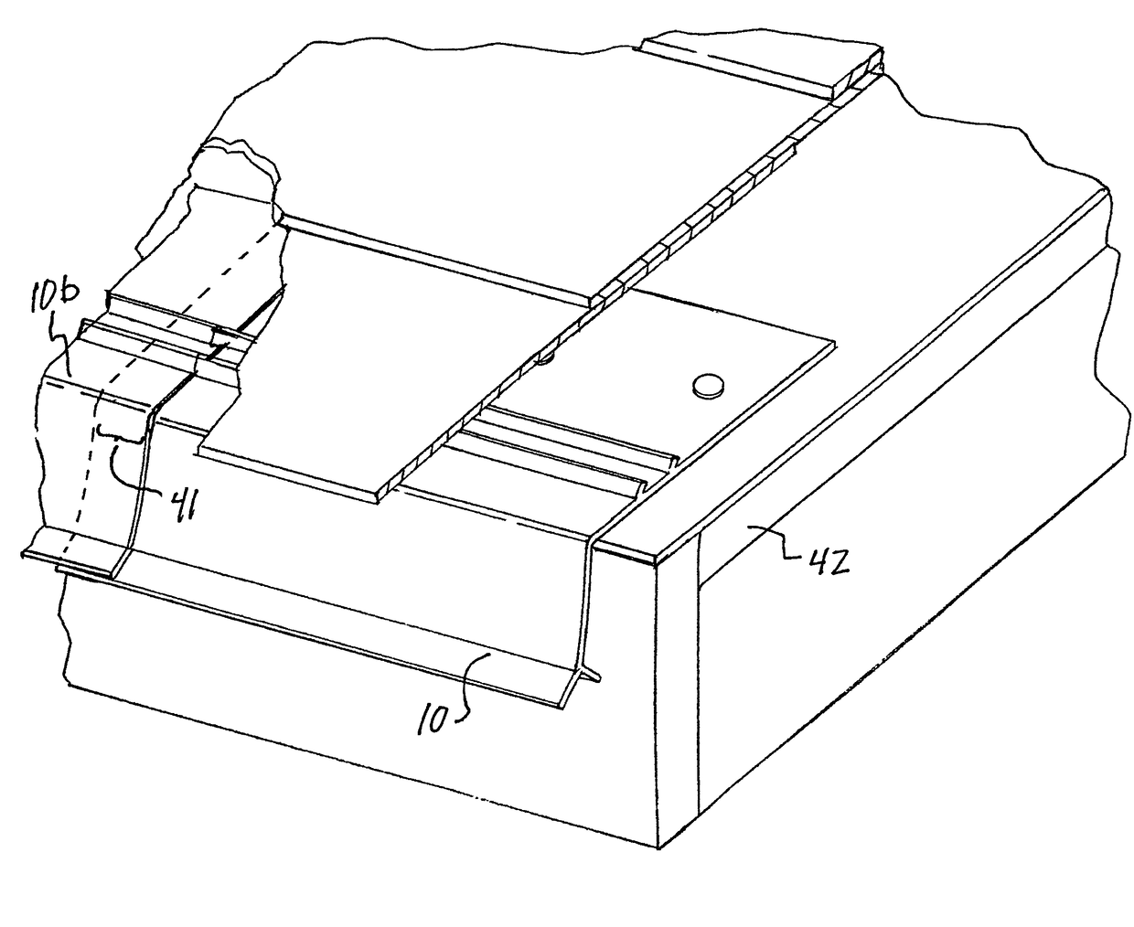
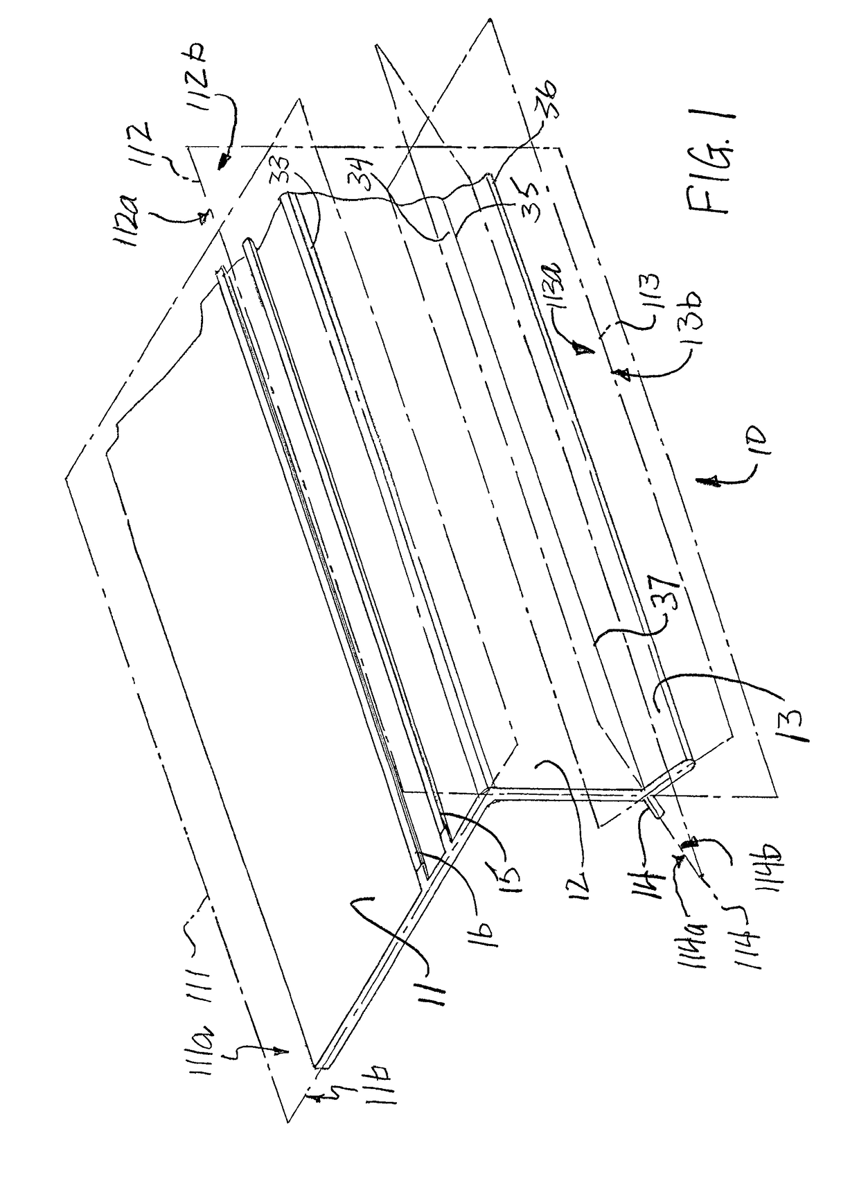
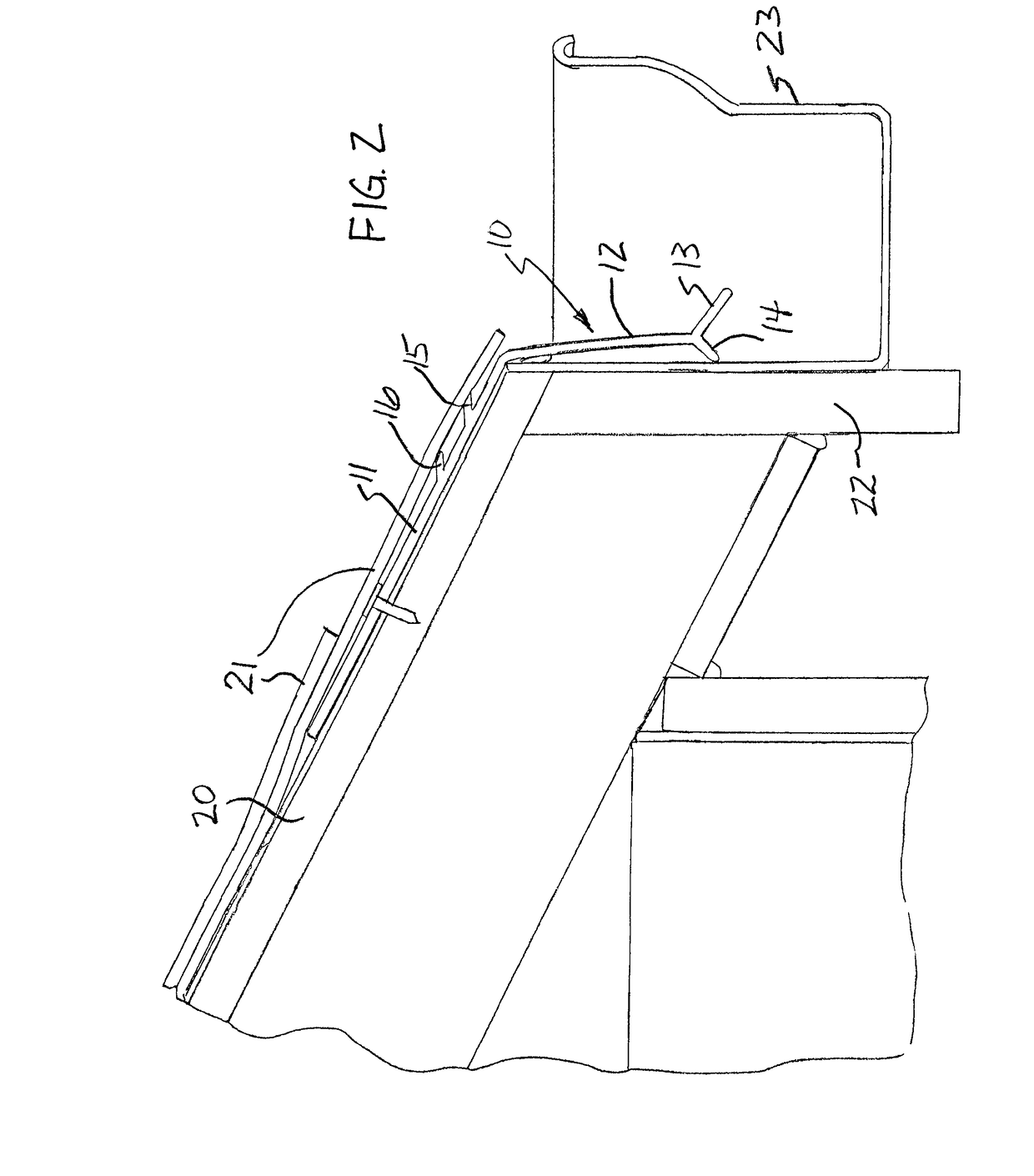
[0032]FIG. 1 shows a roof drip edge 10 according to a first embodiment of the present invention. The drip edge 10 includes a roof leg 11, which is designed to interface with the roof of a building when the drip edge 10 is installed. A down leg 12 is joined to the roof leg, and is designed to extend downwardly from the edge of the roof in front of a fascia board or similar structure at the top of a wall of a building. A drip leg 13 is joined to the down leg 12 and extends at an angle away from the down leg. A back drip leg 14 is also joined to the down leg 12, but it extends from an opposite side of the down leg. As shown in the figures, each of the roof leg 11, down leg 12, drip leg 13, and bac...


PUM


Abstract

A roof drip edge including a roof leg and a drip leg joined to a down leg adapted to protect the intersection of a roof and fascia of a building. Some embodiments include a back drip leg adjacent to the drip leg. Some embodiments include tabs positioned on the roof leg for protection from water infiltration under roof shingles.

Description

FIELD OF THE INVENTION[0001]The present invention is directed to a drip edge for use on a building to direct water away from the building and into a gutter.BACKGROUND OF THE INVENTION[0002]Many buildings include a plurality of upstanding walls covered by a roof. The roof is typically downward sloping and covered by a plurality of shingles. The section of the wall near the roof is often covered by a fascia board for protection and also to allow installation of a gutter to collect water and other debris that rolls off of the roof.[0003]A disadvantage of such roof constructions is that water often seeps between the gutter inner wall and the fascia board, causing rot and deterioration of the fascia board. Moreover, in some types of construction, water can seep between the fascia and the side wall of the building, causing even more extensive damage. Water can also seep in between the roof shingles and the roof boards, causing rot and deterioration of these structural elements.[0004]In an...

Claims


Application Information

Patent Timeline
Patent Type & Authority Applications(United States)
IPC IPC(8): E04D13/04E04D13/158
CPCE04D13/0459E04D2013/0468E04D13/158E04D13/15
Inventor GIVENS, ROBERT D.
Owner DRYFLEKT
Why Eureka
Try Eureka