Connection structure between frame and legs of eyeglasses

a technology of connecting structure and eyeglasses, which is applied in the field of eyeglasses, can solve the problems of increasing production cost, complicated hinge assembly, and more complicated production and installation of eyeglasses, and achieves the effects of saving production cost, convenient installation, and simple structur

Inactive Publication Date: 2017-08-10
HUAMAO OPTICAL IND XIAMEN
View PDF0 Cites 8 Cited by
  • Summary
  • Abstract
  • Description
  • Claims
  • Application Information

AI Technical Summary

Benefits of technology

[0021]1. Through the cooperation between the rotating shaft of the leg and the rotating shaft base of the frame, the leg can be folded or unfolded. The connection of the frame and the leg don't need screws. It is convenient for installation. By using the elasticity of the upper clip, and the intermediate clip, and the lower clip, the extent of the leg to be unfolded can be adjusted for comfortable wear.
[0022]2. Through the cooperation between the rotating shaft of the leg and the rotating shaft base of the frame, the leg can be folded or unfolded. The structure is simpler so as to save the production cost, and it is convenient for installation.
[0023]3. Through the cooperation between the rotating shaft of the leg and the rotating shaft base of the frame, the leg can be folded or unfolded. There is no need for the procedure to lock the screw, so the production and installation cost of the eyeglasses can be reduced.

Problems solved by technology

It is more complicated for production.
The hinge itself is more complicated, so the production and installation of the eyeglasses are minute and complicated to increase the production cost.
After a period of time to fold and unfold the leg, the screws may loosen, rendering that the eyeglasses cannot be used.
This increases the production cost of the eyeglasses.

Method used


Image

  • Connection structure between frame and legs of eyeglasses
  • Connection structure between frame and legs of eyeglasses
  • Connection structure between frame and legs of eyeglasses

Examples


Embodiment Construction

[0027]Embodiments of the present invention will now be described, by way of example only, with reference to the accompanying drawings.

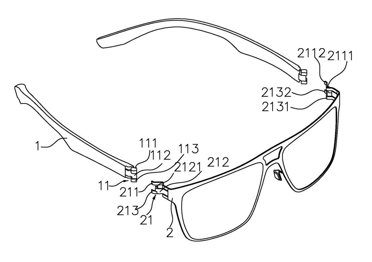
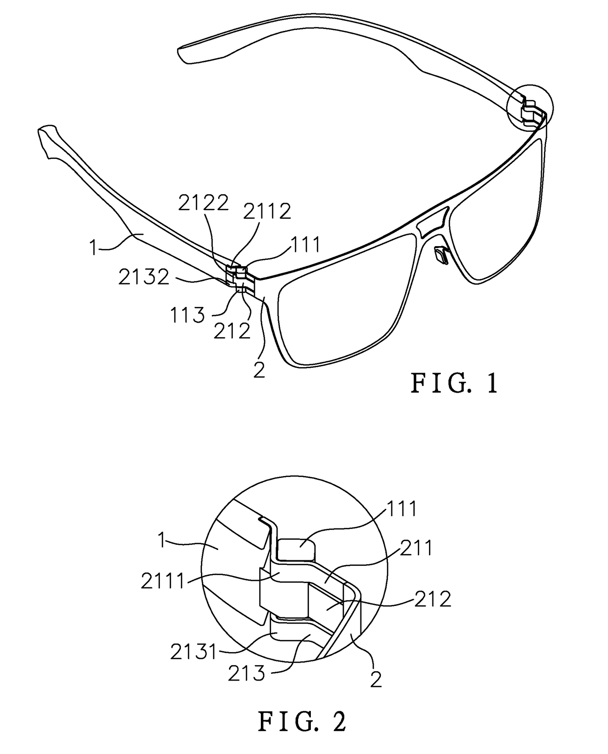
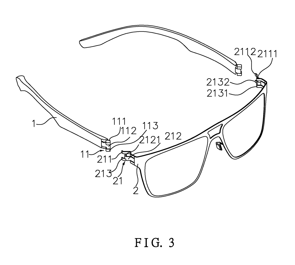
[0028]As shown in FIG. 1 to FIG. 3, the present invention discloses a connection structure between a frame and legs of eyeglasses. A pivoting end of a leg 1 is formed with a rotating shaft 11. A pivoting end of a frame 2 is formed with a rotating shaft base 21. The rotating shaft base 21 of the frame 2 has an upper clip 211, an intermediate clip 212, and a lower clip 213 extending therefrom. The intermediate clip 212 is staggered with the upper clip 211 and the lower clip 213. The rotating shaft 11 of the leg 1 is clamped between the intermediate clip 212, the upper clip 211, and the lower clip 213. The rotating shaft 11 of the leg 1 rotates between the intermediate clip 212, the upper clip 211, and the lower clip 213 so as to fold or unfold the leg 1. The present invention has a simple structure and can be installed conveniently.

[0029]The aforesaid u...


PUM


Abstract

Provided is a connection structure between a frame and legs of a pair of eyeglasses. A pivoting end of a leg is formed as a rotating shaft; correspondingly a pivoting end of a frame is formed as a rotating shaft base; an upper clip, an intermediate clip, and a lower clip extend from the rotating shaft base of the frame; the intermediate clip is staggered with the upper clip and the lower clip, the rotating shaft of the leg is clamped between the intermediate clip, the upper clip and the lower clip, and the rotating shaft of the leg rotates between the intermediate clip, the upper clip and the lower clip, enabling the leg to fold closed and open. The connection between the frame and the leg is screw-less, providing a simple structure, convenient installation, and comfortable wear.

Description

BACKGROUND OF THE INVENTION[0001]1. Field of the Invention[0002]The present invention relates to a pair of eyeglasses, and more particularly to a connection structure between a frame and legs of eyeglasses.[0003]2. Description of the Prior Art[0004]Normally, a conventional connecting structure of a frame and a leg is a hinge connecting structure. Through the hinge, the leg is pivotally connected to the frame, so that the leg can be folded or unfolded through the hinge. However, it has the following drawbacks in use.[0005]1. For the hinge structure, both the leg and the frame are provided with hinges. It is more complicated for production. The hinge itself is more complicated, so the production and installation of the eyeglasses are minute and complicated to increase the production cost.[0006]2. The hinge structure needs screws to lock the leg and the frame. After a period of time to fold and unfold the leg, the screws may loosen, rendering that the eyeglasses cannot be used.[0007]3....

Claims


Application Information

Patent Timeline
Patent Type & Authority Applications(United States)
IPC IPC(8): G02C5/22G02C5/14
CPCG02C5/2209G02C2200/22G02C5/2254G02C5/146G02C5/22G02C2200/12G02C2200/04G02C2200/08
Inventor CHEN, TSUNG-WEN
Owner HUAMAO OPTICAL IND XIAMEN
Why Eureka
Try Eureka