Marker Device

a technology of marking device and marking plate, which is applied in the direction of electrical equipment, identification of installed cables, fastening devices, etc., can solve the problems of not being able to clearly see the visual marker, not being able to easily break or degrade the warning marker, and being forced into an orientation which is more difficult to view,

Inactive Publication Date: 2017-09-28
BALMORAL ENG PTY LTD
View PDF9 Cites 7 Cited by
  • Summary
  • Abstract
  • Description
  • Claims
  • Application Information

AI Technical Summary

Benefits of technology

[0012]It may be advantageous to pro

Problems solved by technology

These warning markers can easily break or degrade and are not easily visible in certain orientations, particularly due to the relatively narrow dimensions of the device.
This can cause a number of issues, namely that there is no visual marker clearly visible while a person is oriented in any direction, such as a direction parallel to the face of the marker.
In addition, if there are strong winds the markers may be forced into an orientation which is more difficult to view, such as the face of the marker being substantially parallel with the relative ground level.
Further, known warning markers typically induce an adverse loading on transmission lines, not only due to the weight of the marker, but also due to wind loading of the marker.
Wind loading of transmission lines can cause damage and potentially cause blackouts or other electrical issues which are costly to repair.
Other known markers, such as obstruction marking spheres, may provide visual warning in multiple orientations however these devices are cumbersome and are not easily attachable to transmission lines.
Notably, t

Method used


Image

  • Marker Device
  • Marker Device
  • Marker Device

Examples


Embodiment Construction

[0037]Preferred embodiments of the invention will now be described with reference to the accompanying drawings and non-limiting examples.

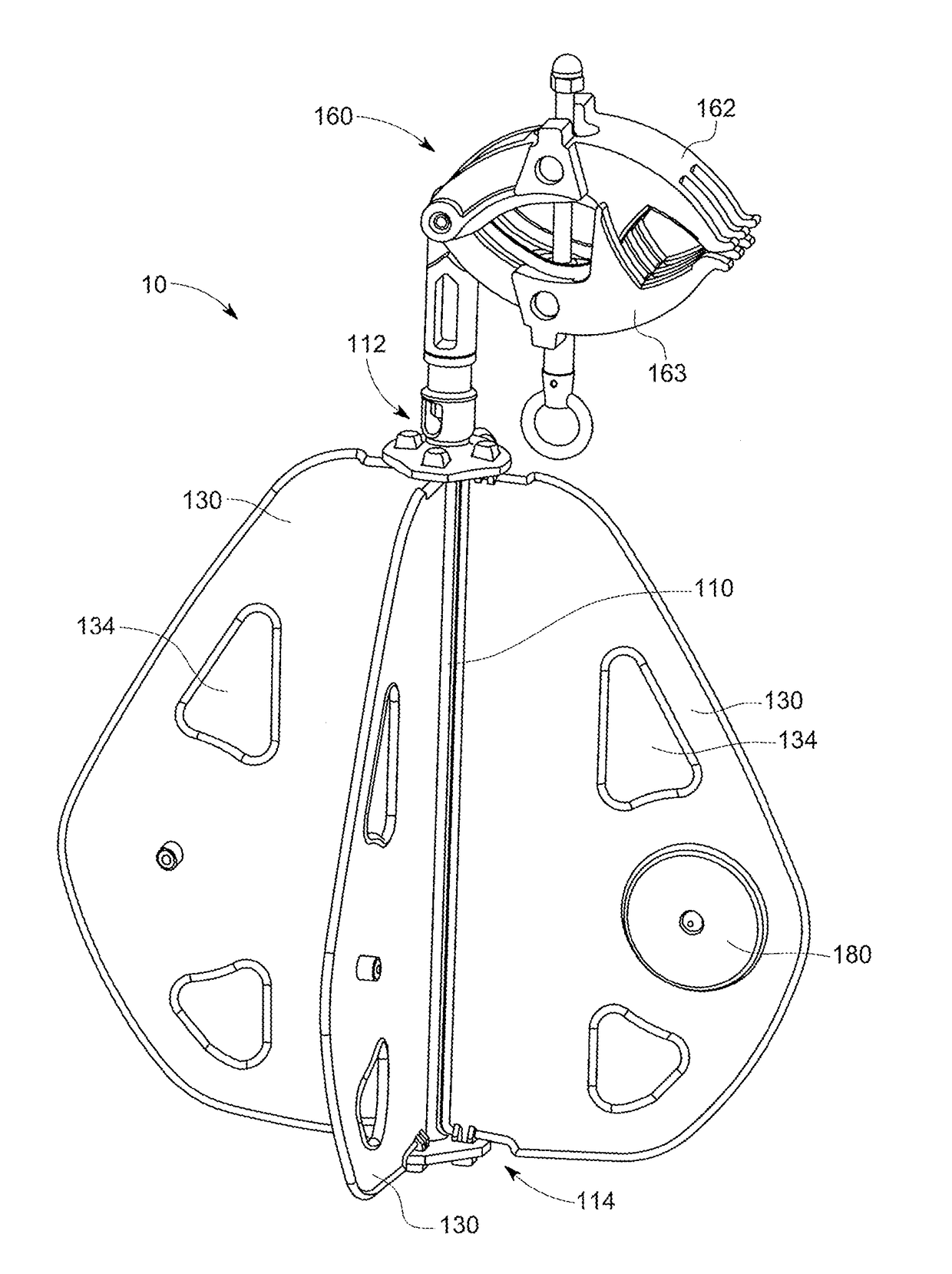
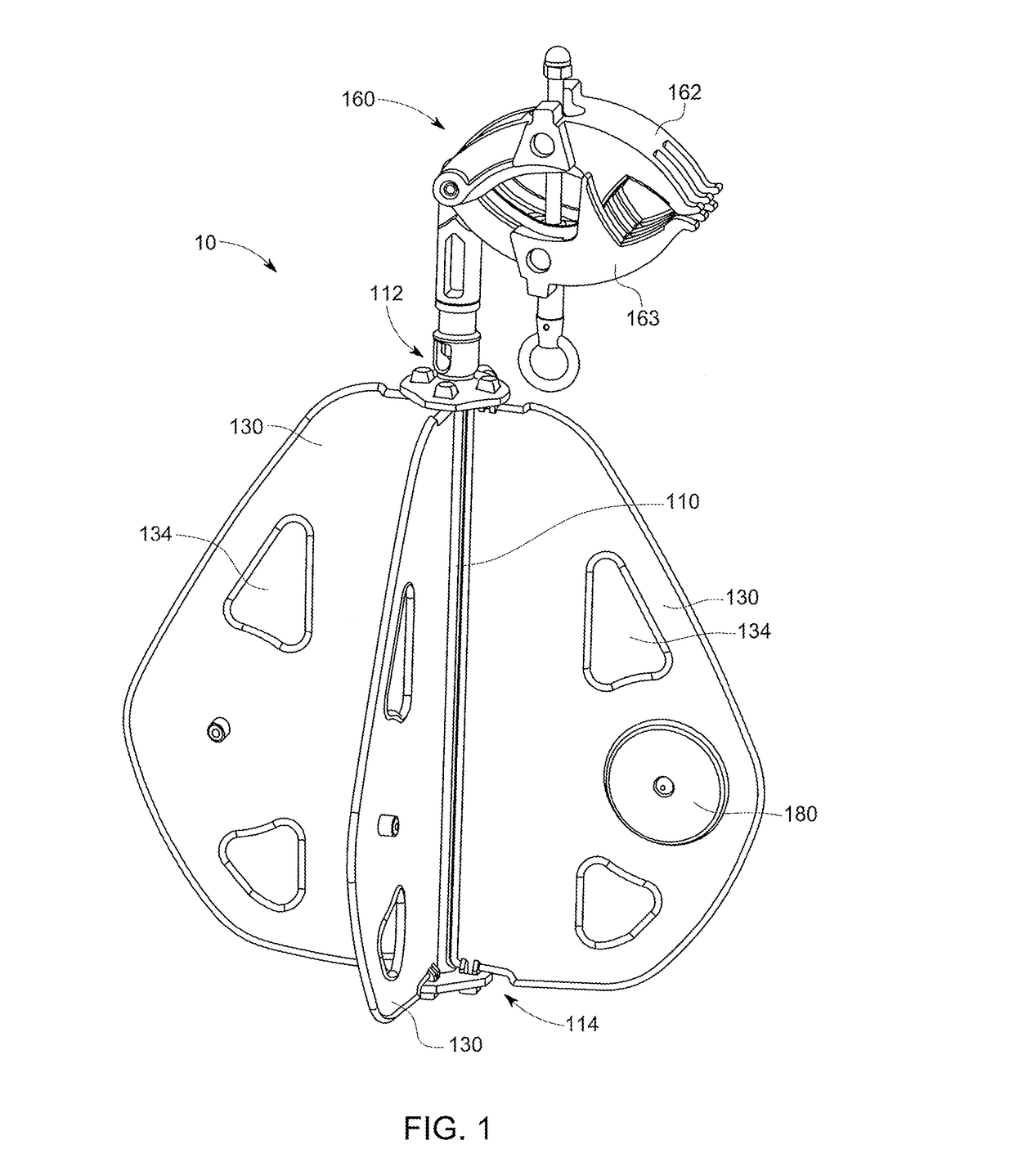
[0038]The present disclosure is directed towards a device adapted for use with powerlines or transmission lines. The device is preferably adapted to be a warning marker and / or preferably allows the marker to be observed from a number of directions. The device preferably allows the marker to be predominantly visible from a direction which is parallel and / or perpendicular to transmission lines. A direction parallel to the line may also be referred to as ‘along the line’. Throughout this specification, the term “transmission line” may also refer to a power line, a distribution line or any other line or cable.

[0039]In at least one embodiment the device 10 is adapted to be viewed from a direction substantially parallel to transmission lines. Viewing the device 10 from multiple directions is advantageous as this may reduce the potential for transmission ...


PUM


Abstract

A device adapted for use as a warning marker. The device comprising a device body with a first end and a second end, in which the first end and the second end define a longitudinal axis therebetween. A securing means may be attached to the device body first end. The device body comprising at least one projection projecting at an angle from the longitudinal axis of the device body; and wherein the device body is rotatable about the axis relative to securing means.

Description

[0001]The present application claims priority to Australian Patent Application No. 2016901106, filed on Mar. 23, 2016, and Australian Patent Application No. 2016901814, filed on May 16, 2016, which are incorporated herein by reference in their entirety.FIELD OF THE INVENTION[0002]The present disclosure relates to a marker device adapted for attachment to an electrically charged item or other suitable object. More particularly, the device adapted to be a visual marker which provides improved visibility and preferably reduces loading on a transmission line, distribution line, power line or other lines relative to known warning markers.BACKGROUND OF THE INVENTION[0003]Warning markers are commonly used to highlight transmission lines such that transmission lines are not inadvertently touched or impacted upon. Warning markers are typically required for a number of purposes such as for; warning planes, allowing birds to differentiate transmission lines from a horizon, cable car applicatio...

Claims


Application Information

Patent Timeline
IPC IPC(8): H02G7/00F16B2/10F16M13/02
CPCH02G7/00H02G2200/20F16B2/10F16M13/022H02G1/02
Inventor MESETI, ENZO
Owner BALMORAL ENG PTY LTD
Why Eureka
Try Eureka