Footrest-foldable wheelchair

a wheelchair and footrest technology, applied in wheelchairs/patient conveyances, medical transportation, ambulance services, etc., can solve the problems of user's foot slipping off the footrest plate through the space, and the distance between the right and left footrest plates is larger

Inactive Publication Date: 2017-10-05
SWANY
View PDF5 Cites 5 Cited by
  • Summary
  • Abstract
  • Description
  • Claims
  • Application Information

AI Technical Summary

Benefits of technology

[0007]According to this wheelchair, since the distance between the fore ends of the footrest arms in the arm unfolded position is smaller so that the space between the footrest plates is narrow in the plate unfolded position, the possibility can be reduced that user's foot slips off the right or left footrest plate through the space between the footrest plates when the user of the wheelchair is putting user's feet on the footrest plates. In the arm folded position, since the distance between the fore ends of the footrest arms can larger, interference between the user and the footrest plates can be reduced when the footrest plates are folded.
[0042]According to this wheelchair, the protrusions on the one of the footrest plates can prevent user's foot from getting into the recessed part, in other words, prevent that user's one foot is located lower than another foot. Additionally, since the central plate has hollows in which the protrusions can fit, the central plate can be accommodated without interference with the protrusions when the central plate is accommodated into the footrest plate.

Problems solved by technology

For this reason, there is a problem that the distance between the right and left footrest plates 242 is larger than the conventional wheelchair shown in FIG. 22.
As a result, the user's foot may slip off the footrest plate through the space.

Method used


Image

  • Footrest-foldable wheelchair
  • Footrest-foldable wheelchair
  • Footrest-foldable wheelchair

Examples


first embodiment

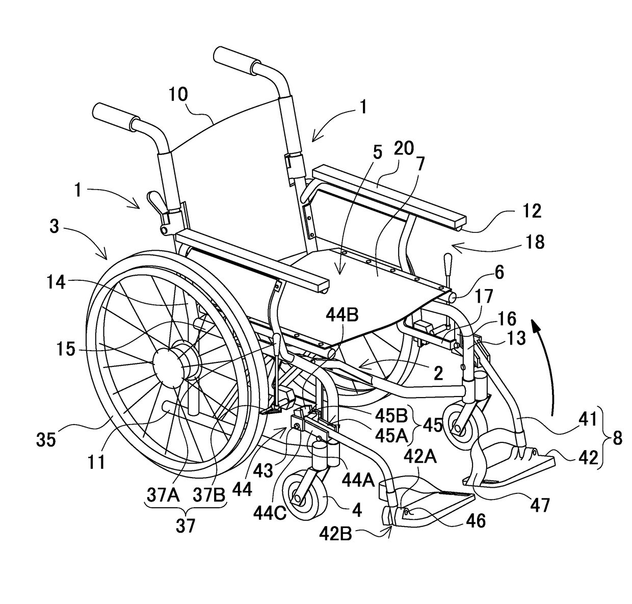
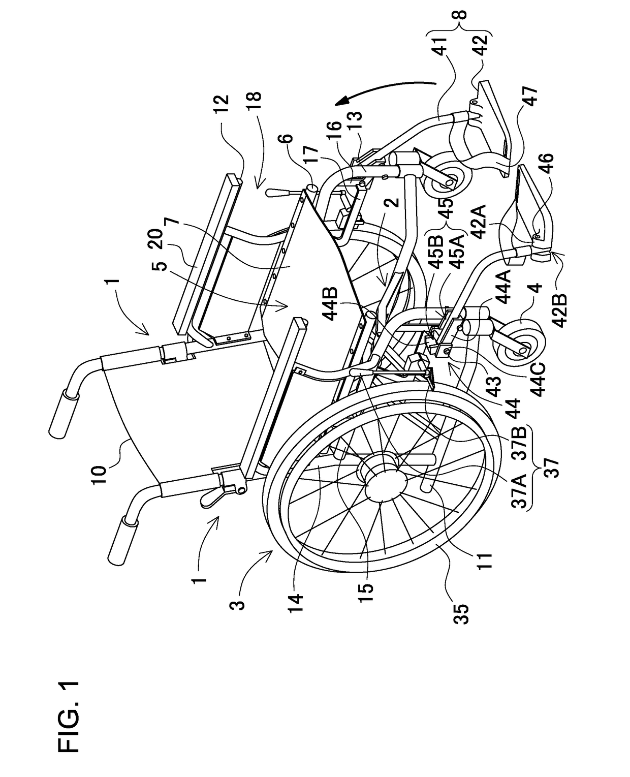
[0070]FIG. 1 is a perspective view showing a wheelchair according to a first embodiment. The wheelchair shown in FIG. 1 includes driving wheels 3, a pair of side frames 1, foldable links 2, seat frames 6, a flexible seat 7, casters 4, and footrests 8. The driving wheels 3 are coupled to the exterior sides of the side frames 1. The foldable links 2 couples the pair of side frames 1 to each other. The seat frames 6 are coupled to the top ends of the foldable links 2. The flexible seat 7 is coupled to the seat frames 6 of the foldable links 2. The casters 4 are coupled to the front parts of the side frames 1, and are free to swivel in the horizontal direction. The footrests 8 are coupled to the side frames 1. Each of the footrests 8 includes a footrest plate 42 that supports user's foot on its upper surface in an unfolded position, and a footrest arm 41 that is coupled to the side frame 1. The footrest plate 42 is coupled to the footrest arm 41. The side frames 1 of the wheelchair are ...

second embodiment

[0102]FIG. 8 is a plan view of a wheelchair according to a second embodiment. In the illustrated wheelchair, the footrest arms 41 are coupled to the exterior sides of the side frames 1 through the arm pivot shafts 43. The footrest arm 41 can be switched between the arm folded and unfolded positions.

(Arm Pivot Shaft 43)

[0103]The arm pivot shaft 43 is inclined in the horizontal plane of the wheelchair as shown in the plan view of FIG. 8. The illustrated arm pivot shaft 43 is inclined so that one of the both ends of the arm pivot shaft, which is located on the exterior side of the wheelchair, is positioned on the front side relative to another end, which is located on the interior side of the wheelchair. The angle of the arm pivot shaft 43 relative to a direction perpendicular to the side frame 1 is defined as an inclination angle γ. The inclination angle γ falls within the range from 1° to 30°. The inclination angle γ preferably falls within the range from 5° to 20°. The inclination a...

modified embodiment 1

[0109]The wheelchairs according to the first and second embodiments have been described. However, the way of reducing the gap between the right and left footrest plates in the plate unfolded position of the footrest plate is not limited to these. In the foregoing embodiments, even in the case where the footrest plates 42 has a roughly rectangular shape, the right and left plate pivot shafts 46 are inclined relative to the extension direction of the footrest arm 41 so that the opposed edges of the right and left footrest plates 42 are parallel to each other, and the gap between the opposed edges is constant. In a wheelchair according to a modified embodiment, the plate pivot shafts 46a are parallel to the extension direction of the footrest arms 41 but the opposed edges of the footrest plates 42 are parallel to each other, and the gap between the opposed edges is constant.

[0110]FIG. 10 is a plan view of the wheelchair according to this modified embodiment. Plate pivot shafts 46a for ...


PUM


Abstract

A wheelchair is provided which includes driving wheels, side frame, footrest arms, and footrest plates. The driving wheels are rotatably coupled to the exterior sides of the side frames. The footrest arms are movable between arm unfolded and folded positions. Each of the footrest arms is pivotably coupled to an arm pivot shaft. The arm pivot shaft is positioned on the exterior side of each of the side frames in front of each of the driving wheels. The footrest plates can support user's feet. Each of the footrest plates is coupled to the fore end of each of the footrest arms. The distance between the fore ends of the footrest arms in the arm unfolded position is smaller than the distance in the arm folded position.

Description

CROSS-REFERENCE TO RELATED APPLICATIONS[0001]The present application claims priority under 35 U. S. C. §119 to Japanese Patent Application No. 2016-074,666, filed Apr. 1, 2016. The contents of this application are incorporated herein by reference in their entirety.BACKGROUND OF THE INVENTION1. Field of the Invention[0002]The present invention relates to a footrest-foldable wheelchair.2. Description of the Related Art[0003]A wheelchair includes footrests that support user's feet when the user is sitting down (see Laid-Open Patent Publication No. JP 2009-011,691 A). As shown in FIG. 22, the footrests 108 of this wheelchair protrude frontward under a flexible seat (sheet) 107 so that the user can comfortably put user's feet when sitting on the flexible seat 107. Each of the footrests 108 includes a footrest arm 141, and a footrest plate 142 that is coupled to the fore end part of the footrest arm and can pivot between plate unfolded and folded positions. The footrest plate 142 of this ...

Claims


Application Information

Patent Timeline
Patent Type & Authority Applications(United States)
IPC IPC(8): A61G5/12A61G5/08
CPCA61G5/085A61G5/128A61G5/04A61G5/12A61G5/0825A61G5/0833
Inventor ITANO, TSUKASA
Owner SWANY
Why Eureka
Try Eureka