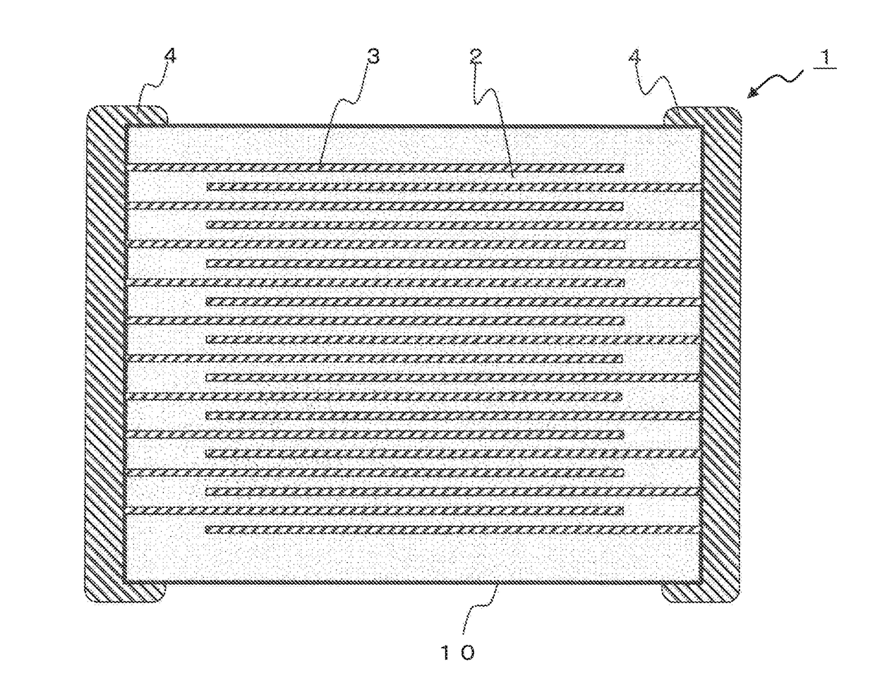
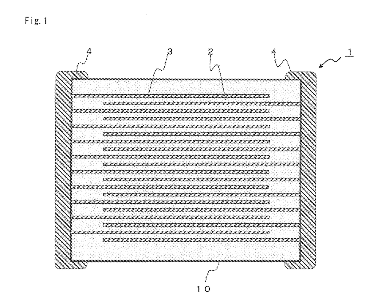
Dielectric ceramic composition and multilayer ceramic capacitor

a technology of ceramic capacitors and dielectric ceramics, applied in the direction of fixed capacitors, basic electric elements, electrical appliances, etc., can solve the problems of reducing the effective capacity or reliability under the used environment, reducing the permittivity and insulation resistance or so, etc., and achieve good ir characteristic, good specific permittivity, and high temperature accelerated lifetime

Active Publication Date: 2017-10-05
TDK CORPARATION
View PDF0 Cites 17 Cited by
  • Summary
  • Abstract
  • Description
  • Claims
  • Application Information

AI Technical Summary

Benefits of technology

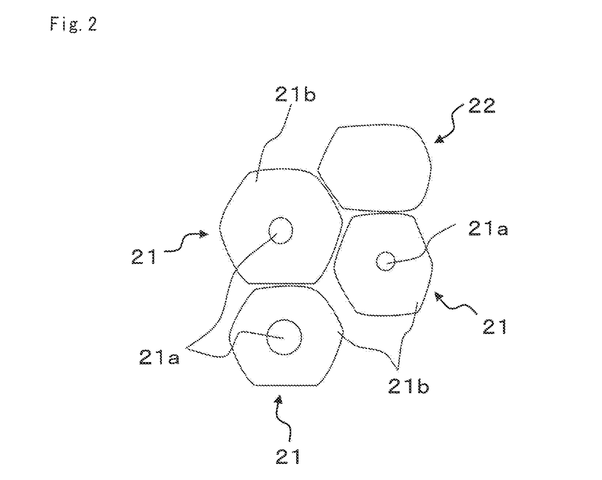
[0019]According to the present invention, by setting the content of each component within the above range, and by setting the area ratio between the main component phase and the diffusion phase and also the composition of the diffusion phase within the above mentioned range, the dielectric ceramic composition having particularly good IR characteristic and high temperature accelerated lifetime can be obtained. By setting the composition of the diffusion phase within the specific range, the basic characteristics such as the specific permittivity can be maintained good, and also the IR characteristic and the high temperature accelerated lifetime can be improved.

Problems solved by technology

In case of using it at a high rated voltage as mentioned in the above, it is used under high electric field intensity, but if the electric field intensity becomes higher, the specific permittivity and the insulation resistance or so decreases, hence as a result, the effective capacity or the reliability under the used environment may decrease.
However, the multilayer ceramic capacitor described in the patent document 1 exhibited insufficient characteristic under a high electric field intensity such as when applying DC voltage or so, and thus further improvement of the characteristics were demanded.

Method used


Image

  • Dielectric ceramic composition and multilayer ceramic capacitor
  • Dielectric ceramic composition and multilayer ceramic capacitor
  • Dielectric ceramic composition and multilayer ceramic capacitor

Examples


example

[0101]Hereinafter, the present invention will be described based on the further detailed examples, but the present invention is not limited to the examples.

(Preparation 1 of the Dielectric Materials) Samples 1 to 26

[0102]As the main component material, barium carbonate (BaCO3), calcium carbonate (CaCO3), strontium carbonate (SrCO3), titanium oxide (TiO2) and zirconium oxide (ZrO2) were prepared. Further, the rare earth oxides as the first sub component material, and oxides of Si and Al as the second sub component material, and magnesium oxide (MgO) as the third sub component and oxides of Mn and Cr as the material of the fourth sub component were prepared.

[0103]Said main component and sub components were weighed so that the composition after the firing satisfies the composition shown in Table 1. After weighing each material, each material were mixed. The mixing was carried out for 20 hours by a ball mill using wet mix stirring. The compound obtained after the wet mix stirring was de...


PUM

PropertyMeasurementUnit
thicknessaaaaaaaaaa
thicknessaaaaaaaaaa
thicknessaaaaaaaaaa

Abstract

A dielectric ceramic composition has good characteristics even under the high electric field intensity, and particularly good IR characteristic and the high temperature accelerated lifetime. The dielectric ceramic composition has a main component having a perovskite type compound shown by a compositional formula (Ba1-x-ySrxCay)m(Ti1-zZrz)O3, a first sub component having oxides of a rare earth element R, a second sub component as a sintering agent, wherein the dielectric particles has dielectric particles having high diffusion rate of the rare earth element, preferably of a complete solid solution particle, and when a concentration of Ti atom in the diffusion phase is 100 atom %, then an average concentration of the rare earth element R in the diffusion phase is 5 atom % or more, and an average concentration of Zr in the diffusion phase is 10 atom % or more.

Description

BACKGROUND OF THE INVENTION1. Field of the Invention[0001]The present invention relates to a dielectric ceramic composition, a multilayer ceramic capacitor including a dielectric layer comprising the dielectric ceramic composition, and particularly the present invention relates to the dielectric ceramic composition having good IR characteristic and a high temperature accelerated lifetime.2. Description of the Related Art[0002]Recently, as the electronic circuit has become highly densified, the electronic component is demanded to be more compact, and the multilayer ceramic capacitor has rapidly become more compact with larger capacity, further the purpose of use has become wider, thus various characteristics are in demand.[0003]For example, the mid-high voltage capacitor which is used at a high rated voltage (for example 100 V or higher) is suitably used for ECM (engine electric computer module), a fuel injection device, an electric controlled throttle, an inverter, a convertor, HID ...

Claims


Application Information

Patent Timeline
Patent Type & Authority Applications(United States)
IPC IPC(8): H01G4/12H01G4/248C04B35/49H01G4/30
CPCH01G4/1245H01G4/30H01G4/248C04B35/49C04B2235/768C04B2235/3213C04B2235/3208C04B2235/3236C04B2235/3249C04B2235/3215C04B35/622C04B2235/662C04B2235/6565C04B2235/6567C04B2235/6562C04B2235/3418C04B2235/3262C04B2235/3241C04B2235/3224C04B2235/3225C04B2235/3217C04B2235/3206C04B35/4682C04B35/6263C04B35/62675C04B35/62685C04B35/6342C04B2235/3232C04B2235/3244C04B2235/442C04B2235/6582C04B2235/6584C04B2235/663C04B2235/75C04B2237/346C04B2237/68C04B2237/704H01G4/1227
Inventor SAKURAI, DANMORIGASAKI, NOBUTOISHII, TATSUYAARIIZUMI, TAKUMAHASHIMOTO, SHINSUKEITO, YASUHIRO
Owner TDK CORPARATION
Why Eureka
Try Eureka