System that emits light to overheated portion of cooking container
a technology of cooking container and cooking support, which is applied in the direction of temperature measurement in household appliances, optical radiation measurement, domestic stoves or ranges, etc., can solve the problems of user difficulty in visually determining whether or not cooking ingredients have been cooked well, user difficulty in notified of overheated portion of cooking container,
- Summary
- Abstract
- Description
- Claims
- Application Information
AI Technical Summary
Benefits of technology
Problems solved by technology
Method used
Image
Examples
first embodiment
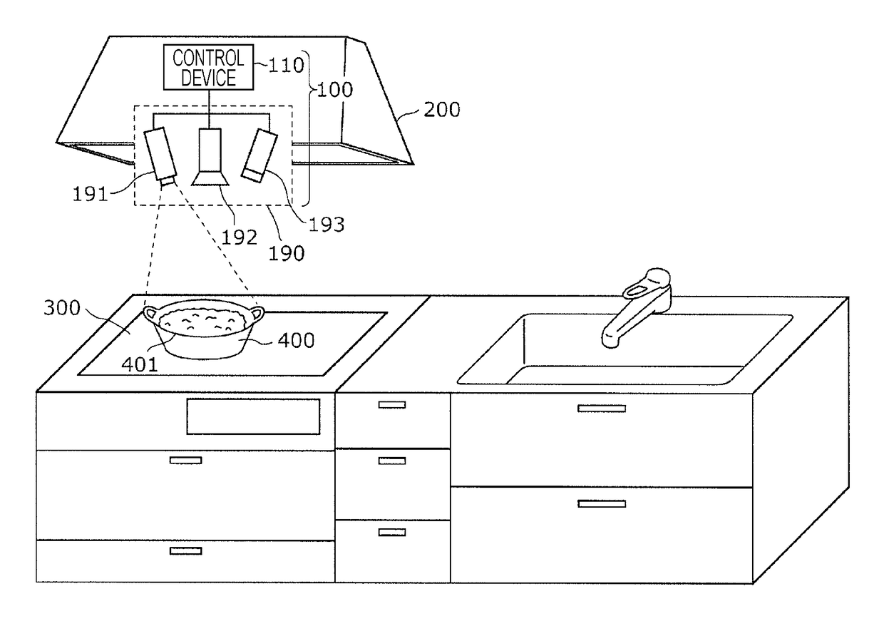
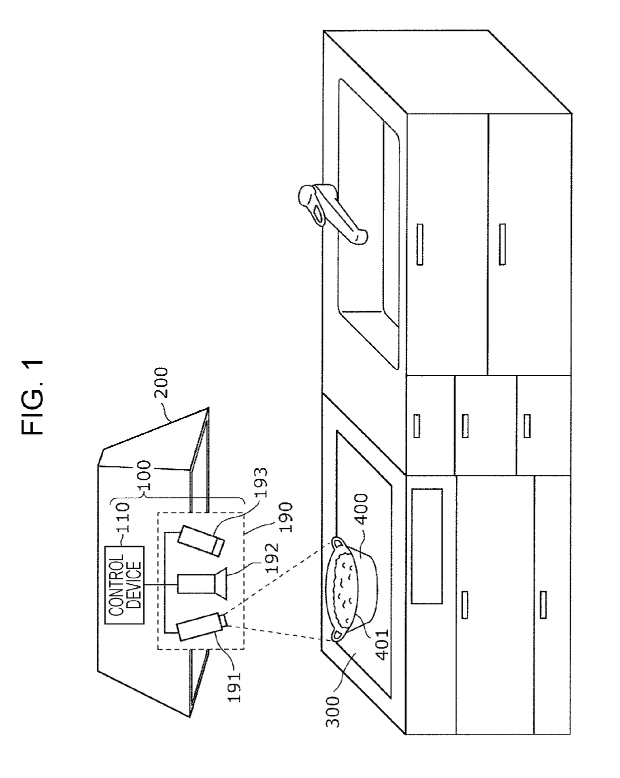
[0062]FIG. 1 is a configuration diagram of a cooking support system in a first embodiment.
[0063]A cooking support system 100 in this embodiment is disposed, for instance, in a range hood fan (hereinafter referred to as a range hood) 200 which is a ventilation fan for a kitchen, and supports heat cooking with an induction heating (IH) cooking heater 300 of a user. It is to be noted that although the cooking support system 100 is exposed from the range hood 200 in FIG. 1 in order to present the configuration of the cooking support system 100 in a comprehensible manner, the cooking support system 100 may be disposed inside the range hood 200. In other words, all or part of the cooking support system 100 may be disposed inside the range hood 200. Also, the IH cooking heater 300 is an example of a cooking device.
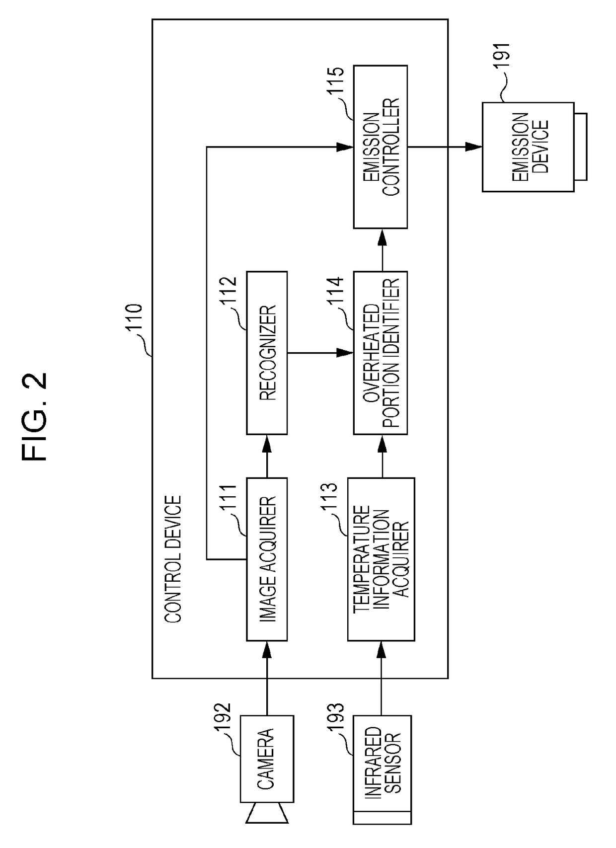
[0064]The cooking support system 100 includes a processing unit 190 that performs processing for supporting heat cooking, and control device 110 which controls the processing uni...
second embodiment
Summary and Effect of Second Embodiment
[0166]In a second embodiment, the detection device includes not only the camera 192U and the infrared sensor 193U, but also the cameras 192R and 192L, and the infrared sensors 193R and 193L. The cameras 192R and 192L capture a range including a cooking container placed in the microwave oven 350 from the lateral side of the cooking container. The infrared sensors 193R and 193L detect the temperatures of portions in ranges captured by respective cameras 192R and 192L. Here, the camera 192R or 192L is a side camera, and the infrared sensor 193R or 193L is a side infrared sensor. The cooking support system 100a includes not only the light emitter 191U, but also the light emitters 191R and 192L that emit light to the cooking container from the lateral side of the cooking container. The light emitters 191R and 192L are side light emitters.
[0167]In the second embodiment, the control device 110a obtains detection information that includes an image (upp...
first modification
of Second Embodiment
[0171]In the second embodiment, the cooking support system 100a emits light to an overheated portion in the right lateral surface 402 and the left lateral surface 403 (that is, the lateral surface) of the cooking container 400b, and does not emit light to any portion (that is, non-overheated portion) other than the overheated portion. In contrast, similarly to the second modification of the first embodiment, the cooking support system 100a in the first modification emits light of a color different from the color of the light emitted to the overheated portion to a non-overheated portion in the lateral surface.
[0172]FIG. 18 illustrates an example of the lateral surface of a cooking container to which light is emitted by the light emitters 191R and 191L.
[0173]Upon obtaining identification area information on a cooking container 400c of the container type “deep”, the emission controller 115a transmits emission instruction information to the light emitters 191R and 19...
PUM
| Property | Measurement | Unit |
|---|---|---|
| temperature | aaaaa | aaaaa |
| temperature | aaaaa | aaaaa |
| temperature | aaaaa | aaaaa |
Abstract
Description
Claims
Application Information
 - R&D
- Intellectual Property
- Life Sciences
- Materials
- Tech Scout
- Unparalleled Data Quality
- Higher Quality Content
- 60% Fewer Hallucinations
Browse by: Latest US Patents, China's latest patents, Technical Efficacy Thesaurus, Application Domain, Technology Topic, Popular Technical Reports.
© 2025 PatSnap. All rights reserved.Legal|Privacy policy|Modern Slavery Act Transparency Statement|Sitemap|About US| Contact US: help@patsnap.com


