
Emergency notification device in radio communication apparatus

a radio communication and emergency notification technology, applied in the field of radio communication equipment, can solve the problems of owner's lost in woods at night, unable to navigate at sea at night, and difficulty in confirming the position of the owner of the radio communication apparatus,

Inactive Publication Date: 2007-12-18
MOTOROLA SOLUTIONS INC
View PDF5 Cites 7 Cited by
  • Summary
  • Abstract
  • Description
  • Claims
  • Application Information

AI Technical Summary

Benefits of technology

[0019]The present invention has been made in view of the problems described above, and it is an object of the present invention to provide a radio communication apparatus including an emergency notification device that uses an indicator lamp, by which an owner of the apparatus can exactly notify his position when he has encountered an emergency as described above.
[0031]When a rescuer comes relatively close to the owner of this transceiver, who has got lost in the woods, the concurrent use of the burst sound and the indicator lamp sometimes becomes effective.

Problems solved by technology

As emergencies encountered by the owner of the radio communication apparatus, it often happens that the owner has got lost in woods at night or navigation at sea at night has become impossible.
However, it often happens that notification of the position of the owner of the radio communication apparatus is difficult; that is, in most cases, there is no target object around the radio communication apparatus.
Thus, unless the radio communication apparatus is equipped with a Global Positioning System (GPS), it is difficult for the owner to exactly clarify his position.
However, the volume of the sound that can be output from the radio communication apparatus is small, in general.
The radio communication apparatus, however, is not so effective in the case where an emergency as described above has been encountered.

Method used


Image

  • Emergency notification device in radio communication apparatus
  • Emergency notification device in radio communication apparatus
  • Emergency notification device in radio communication apparatus

Examples


Embodiment Construction

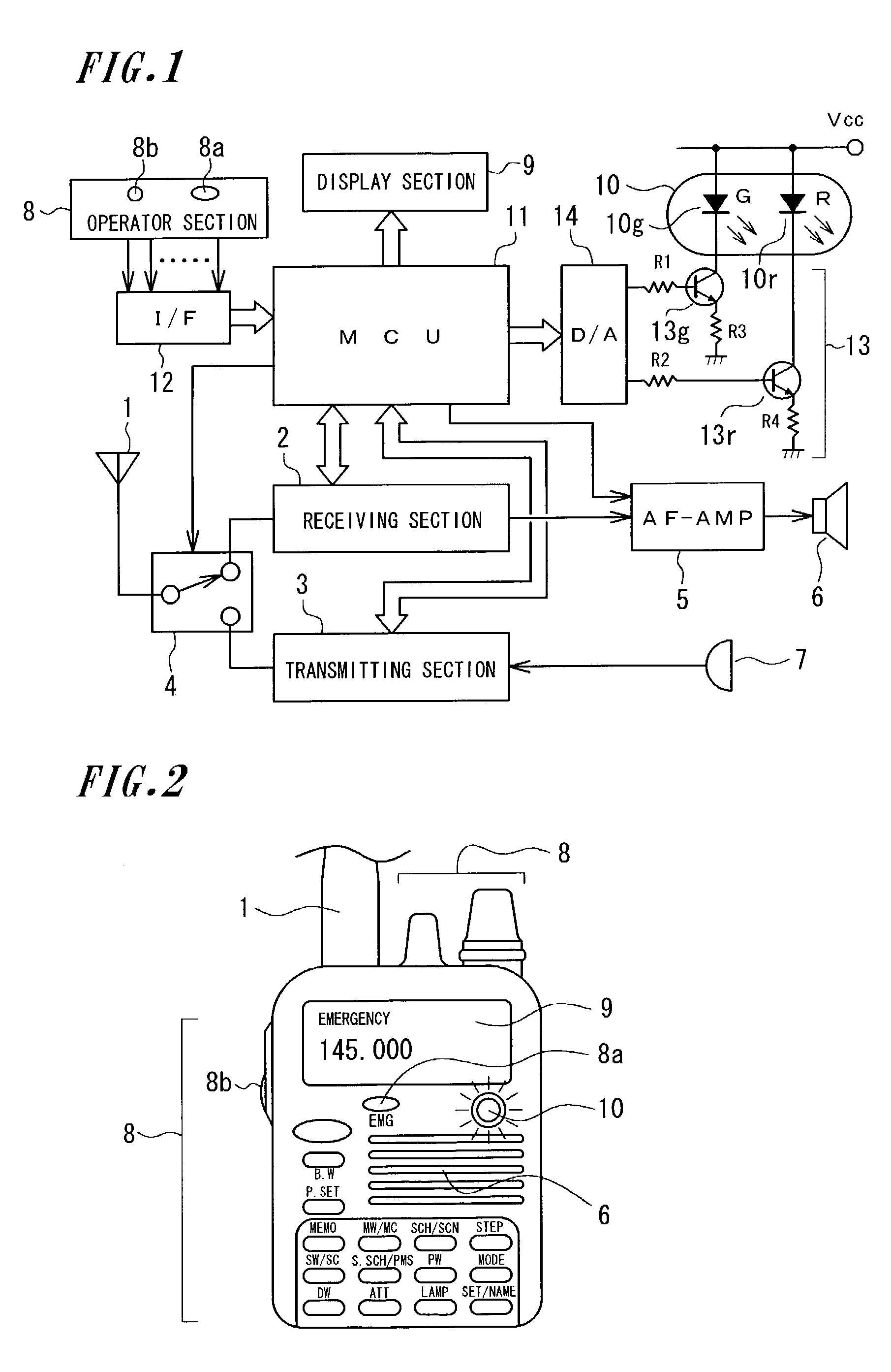
[0040]First, FIG. 1 is a system circuit diagram of a hand-held transceiver.

[0041]Referring to FIG. 1, reference numeral 1 denotes an antenna, reference numeral 2 denotes a receiving section, reference numeral 3 denotes a transmitting section, reference numeral 4 denotes a switching circuit for performing switching between the receiving section 2 and the transmitting section 3 in a receive / transmit mode, for connection to the antenna 1, reference numeral 5 denotes a low-frequency amplifier, reference numeral 6 denotes a loudspeaker, reference numeral 7 denotes a microphone, reference numeral 8 denotes an operator section, reference numeral 9 denotes a liquid crystal display section, reference numeral 10 denotes an indicator lamp, reference numeral 11 denotes a Micro Controller Unit (MCU) for controlling an entire system, reference numeral 12 denotes an input interface of the operator section 8 for the MCU 11, reference numeral 13 denotes drive circuits for the indicator lamp 10, and ...


PUM


Abstract

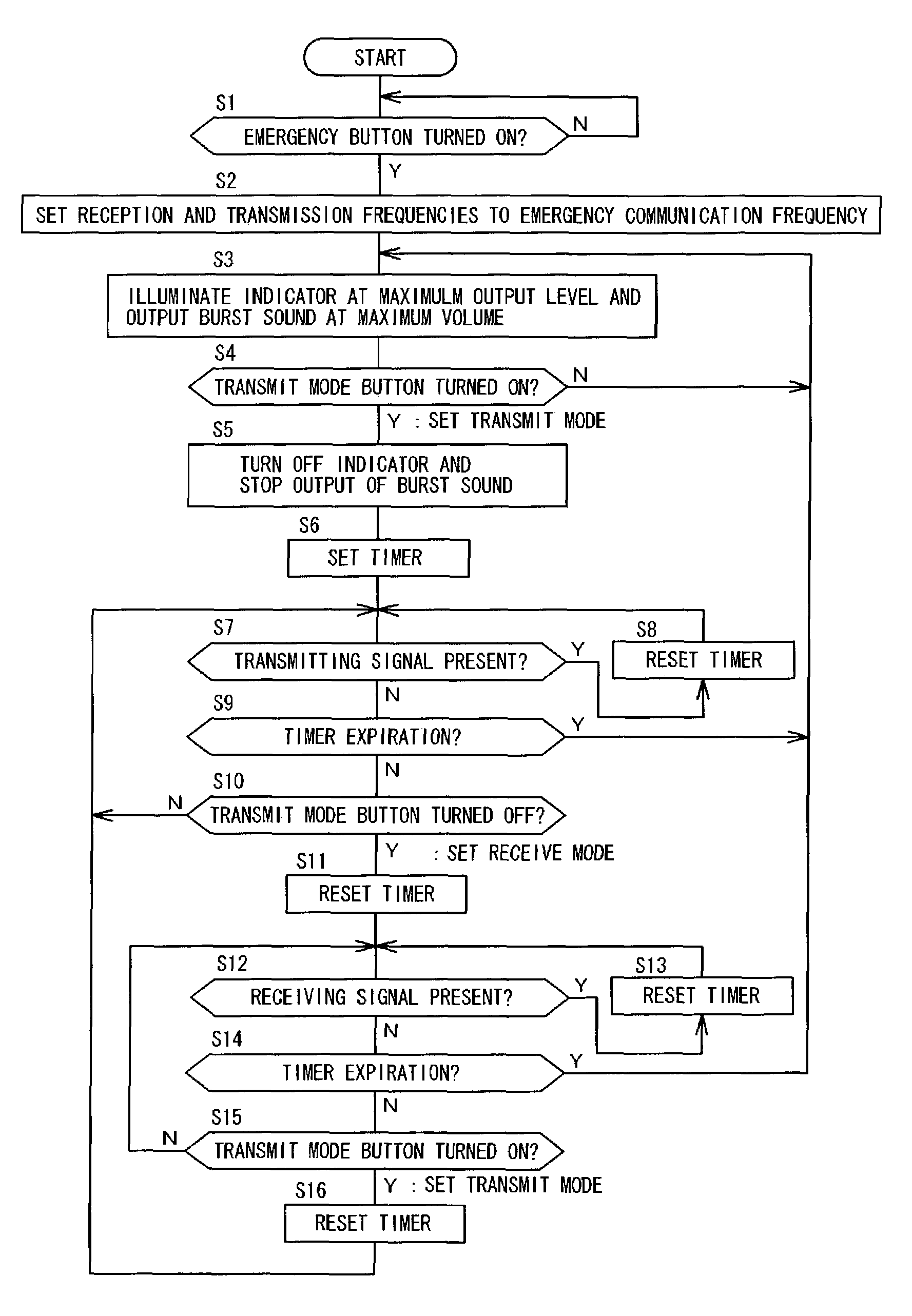
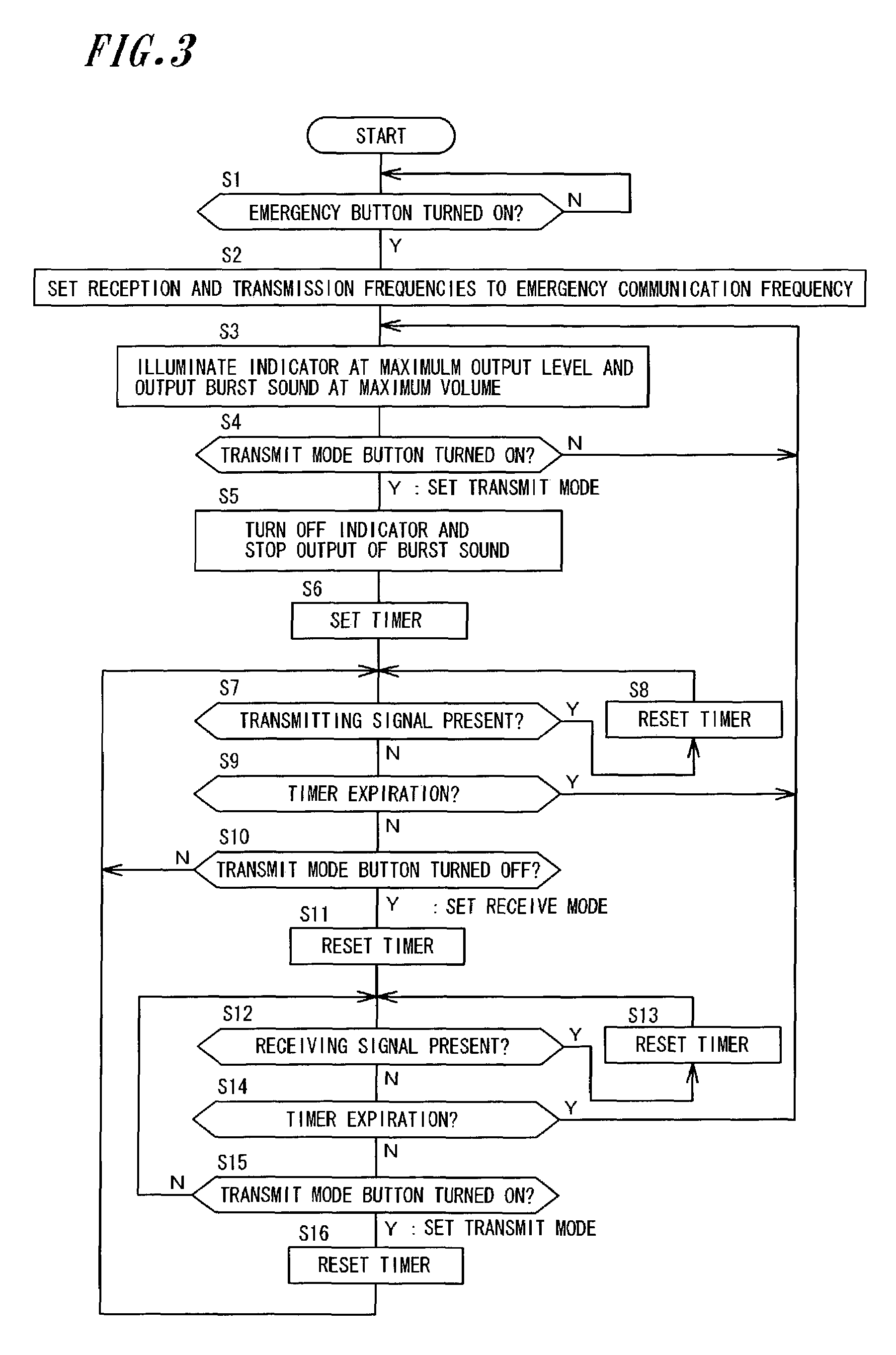
When an emergency button 8a of a radio communication apparatus has been turned ON and a transmit mode button 8b has been depressed, an MCU 11 sets frequencies of a receiving section 2 and a transmitting section 3 to an emergency communication frequency. The MCU 11 also causes an indicator lamp 10 to illuminate or flash at peak intensity, and causes a burst sound to be supplied from a loudspeaker 6 at the maximum volume. Then, the MCU 11 causes a built-in timer to measure a given time period while resetting the timer whenever a reception / transmission switching operation is performed or a communicating signal is detected. While the timer measures the time period, the MCU 11 causes the indicator lamp 10 to be turned off. When a timer expiration is detected, the MCU 11 causes the indicator lamp 10 to be turned on or flashed again.

Description

BACKGROUND OF THE INVENTION[0001]1. Field of the Invention[0002]The present invention belongs to a technical field for a radio communication apparatus, and relates to an emergency notification device in the radio communication apparatus, by which a user of the radio communication apparatus notifies his position through the use of an indicator lamp therein, as well as performs essential emergency communication, when he has encountered an emergency situation such as an accident.[0003]2. Description of the Related Art[0004]When encountering an emergency such as a disaster, radio communication apparatus users have to voluntarily notify a lot of other radio communication apparatus users of the emergency situation.[0005]In the case of amateur radio communication, in particular, it is recommended that a communicating frequency being in use be switched to a CALL frequency specified in each of communication frequency bands, thereby fulfilling the above-mentioned duty.[0006]Since the frequenc...

Claims


Application Information

Patent Timeline
IPC IPC(8): H04B1/38H04M11/04G08B25/01G08B25/10H04B1/04H04W4/90H04W88/02
CPCG08B25/016H04W88/02H04W76/007H04W4/22H04W4/90H04W76/50Y02P70/50
Inventor FUJIKI, SHIRO
Owner MOTOROLA SOLUTIONS INC
Learn More