Joint fusion instrumentation and methods

a joint fusion and instrumentation technology, applied in the field of joint fusion instruments and methods, can solve the problems of large stress across, limited treatment options, and wear of the cartilage of the joint, and achieve the effect of fracture, and reducing the risk of fractur

Active Publication Date: 2017-10-26
IMDS CORPORATION +1
View PDF4 Cites 31 Cited by
  • Summary
  • Abstract
  • Description
  • Claims
  • Application Information

AI Technical Summary

Problems solved by technology

These joints support the entire weight of the upper body when it is erect, placing a large amount of stress across them.
This can lead to wearing of the cartilage of the SI joints.
Treatment options have been limited to conservative care involving physical therapy and joint inje...

Method used


Image

  • Joint fusion instrumentation and methods
  • Joint fusion instrumentation and methods
  • Joint fusion instrumentation and methods

Examples


Embodiment Construction

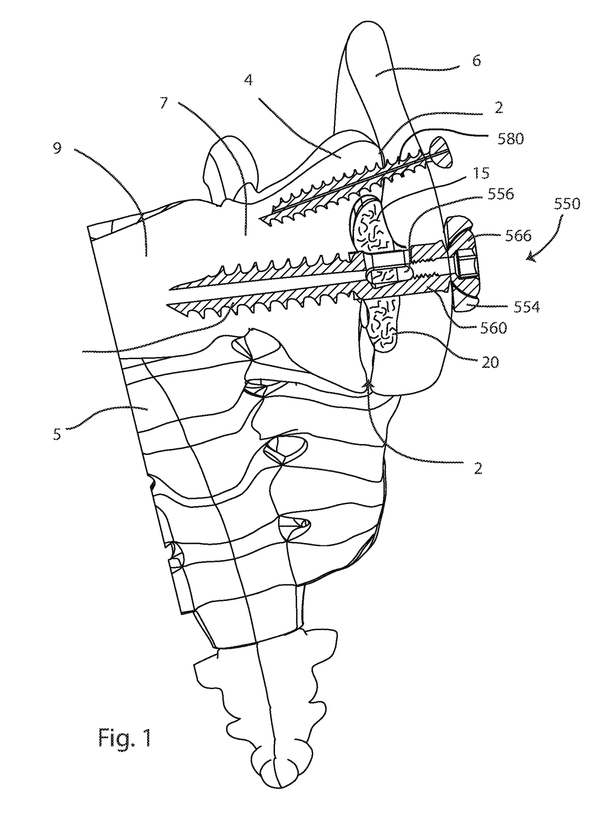
[0045]The present invention relates specifically to systems and methods for fusion of a sacroiliac joint, and more generally to systems and methods for creating a cavity in a bone or joint. Those of skill in the art will recognize that the following description is merely illustrative of the principles of the invention, which may be applied in various ways to provide many different alternative embodiments. This description is made for the purpose of illustrating the general principles of this invention and is not meant to limit the inventive concepts in the appended claims.

[0046]The terms “front”, “side”, “back”, “upper” and “lower” are used herein to identify a relative frame of reference to a particular device or an individual element of a device. In alternate embodiments the front or upper side of a device or element may be established on any desired side of the device or element.

[0047]According to a first aspect of the disclosure, a device for excising a cavity within bony tissue...


PUM


Abstract

Systems and methods for joint preparation and fusion are disclosed. The system includes a cutting device having a handle, and rigid blade member. The blade member may include cutting edges on first and second sides, and may be curved in one or more planes. The blade member may be deployed to project outside of an outer tube, and the cutting device may be rotated to create a circular cavity. In a method of use, a cannula provides access to a procedure site such as a joint. A pathway to the joint is created, and the cutting device is inserted and deployed to undercut a cavity in the joint. A fusion device may be implanted across the joint to provide compression and fuse the joint. The system may also include instrumentation for creating access to a joint, bone graft insertion and implant insertion.

Description

CROSS-REFERENCE TO RELATED APPLICATIONS[0001]None.STATEMENT REGARDING PRIOR DISCLOSURES BY THE INVENTOR OR A JOINT INVENTOR[0002]William W. Cross III is the inventor of the subject matter of U.S. patent application Ser. No. 14 / 790,480, filed on Jul. 2, 2015 and entitled SACROILIAC JOINT FUSION SCREW AND METHOD, published as U.S. Patent Application Publication no. US2016 / 0000488A1. William W. Cross III is an inventor of the subject matter of the present disclosure. The above-identified patent application publication is incorporated herein by reference.BACKGROUND OF THE INVENTION[0003]The present invention relates to instrumentation and methods for the creation of a cavity in a bone or joint. More specifically, the invention relates to instrumentation and methods for creating a cavity in a joint between a sacrum and an ilium, and implants, instrumentation and methods for fusing a sacroiliac joint.[0004]The sacroiliac (SI) joints are formed by the connection of the sacrum and the right...

Claims


Application Information

Patent Timeline
IPC IPC(8): A61B17/16
CPCA61B17/1671A61B17/1637A61B17/864A61B2090/061A61B17/1617A61B17/7098A61B17/846A61B17/7055A61B17/8625A61B17/90A61B17/1615A61F2/30988A61F2/4601A61F2002/30622A61F2002/30995
Inventor RINDAL, BJORN N.SCHUMACHER, BRIAN SCOTTSLATER, NICHOLASCROSS, III, WILLIAM W.
Owner IMDS CORPORATION
Why Eureka
Try Eureka