Oval Compression Unit for Interchangeable Golf Grip

Inactive Publication Date: 2017-10-26
CHALIFOUX PAUL
View PDF14 Cites 0 Cited by
  • Summary
  • Abstract
  • Description
  • Claims
  • Application Information

AI Technical Summary

Benefits of technology

[0027]The present design further allows a golfer to position the grip fully or partially onto a golf club shaft effectively changing golf club length. The internal compression unit must be sufficiently long in a golf club shaft to secure it however, as much as several inches change can be completed by design.
[0028]A golf club shaft diameter decreases as one moves down the shaft

Problems solved by technology

It is difficult to evaluate which grip fits a golfer's hand best and works best as a golfer cannot try them on a golf club and strike balls.
If grips are attached to a golfer's clubs and they do not like them, it is an expensive and time consuming process to replace them.
Present technology to change a golf grip is complex enough that most

Method used


Image

  • Oval Compression Unit for Interchangeable Golf Grip
  • Oval Compression Unit for Interchangeable Golf Grip
  • Oval Compression Unit for Interchangeable Golf Grip

Examples


Embodiment Construction

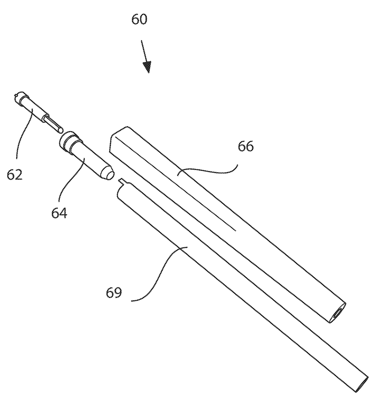
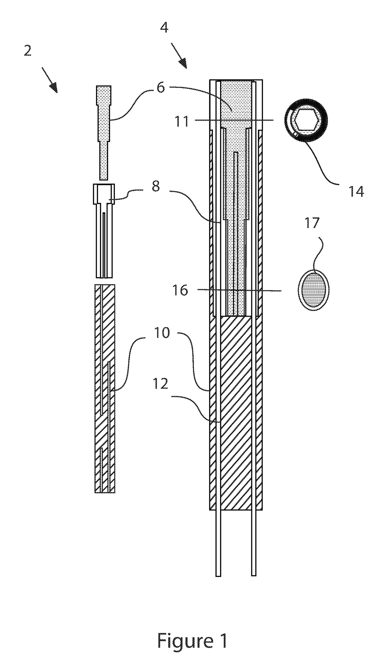
[0048]Referring to FIG. 1, view 2 shows components used while view 4 shows the same components assembled and placed on golf shaft 12. Key 6 fits inside outer component 8, which fits inside and is joined to core 10. When placed on golf shaft 12, outer component 8 with key 6 in it and joined to core 10 fits inside the shaft while core 10 slides outside shaft 12. A rubber component not shown is place onto core 10. Extension 14 seen at cross section 11 limits rotation of key 6 while oval cross section 17 shows oval shape 17 of key 6 lower section which produces outer component expansion when turned

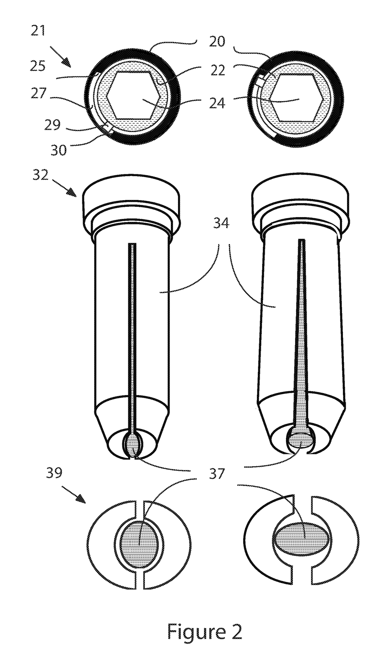
[0049]Referring to FIG. 2, top view 21, side view 32 and bottom view 39 shows a compression unit in the active and inactive position. Illustrations on the left side are in the inactive position while those on the right side are in the active position. Key 22 with hex drive hole 24 is placed into outer component 20. Key 22 rotates when a hex shaped driver turns the key. Key 22 has extension 29 ...


PUM


Abstract

A key includes an out of round cross section which rotates to expand a compression unit in a golf club shaft. The top of the key has an extension which moves in a slot within the compression unit to define the maximum active and inactive positions.

Description

CROSS REFERENCE TO RELATED PATENT APPLICATION[0001]This application is a Continuation-In-Part application and claims benefit of and takes priority from U.S. patent application Ser. No. 15 / 176,200 filed on Jun. 6, 2016, the contents of which are hereby incorporated by reference.BACKGROUND1. Field of the Invention[0002]U.S. patent application Ser. No. 15 / 176,200 describes a golf grip with an internal compression unit. A key is placed in a compression unit which when pressed expands the compression unit. Different cross section diameters of a hole going through the center of a compression unit result in the compression unit expanding when the internal key is pushed or rotated. The present invention rotates an out of round key in a central hole with different cross section diameters to cause expansion. Stops placed at the top of the compression unit define inactive to active compression. The present invention eliminates the use of ramps in the lower portion of the inner hole of an outer...

Claims


Application Information

Patent Timeline
IPC IPC(8): A63B60/16A63B53/14
CPCA63B60/16A63B60/14A63B53/14A63B60/28
Inventor CHALIFOUX, PAUL
Owner CHALIFOUX PAUL
Why Eureka
Try Eureka