Fusible link with coulomb damping

a technology of coulomb damping and friction link, which is applied in the direction of shock absorbers, gearing details, machines/engines, etc., can solve the problems of severe shock, extreme unpredictable blade-off event load, and major damage to the working engin

Active Publication Date: 2017-10-26
HAMILTON SUNDSTRAND CORP
View PDF3 Cites 3 Cited by
  • Summary
  • Abstract
  • Description
  • Claims
  • Application Information

AI Technical Summary

Benefits of technology

[0005]Technical function of the embodiments described above includes that the female link receives the male link to allow translation of the male link relative to the female link and to form a radial interface, wherein the radial interface dampens translation of the male link relative to the female link, and a pin releasably coupled to the male link and the female link to selectively retain the male link and the female link.

Problems solved by technology

The most extreme loads come from so-called “blade-off” events, when blades of the engine detach due to impacts or the like, causing severe shocks and often major damage to the working engines.
Blade-off event loads are extremely unpredictable, but can be more than an order of magnitude stronger than any other sudden or extreme shock gas turbine engines are expected to experience, such as impacts due to hard landings.
Extreme loads can cause damage to the gearbox itself, as well as to attached peripheral systems driven by the gearbox.
In addition, extreme loads that damage or disconnect parts of the gearbox from the engine can result in potentially dangerous oil leakages.
Often, conventional gearboxes and gearbox connections may require additional material or be heavier to withstand such extreme loads.

Method used


Image

  • Fusible link with coulomb damping
  • Fusible link with coulomb damping
  • Fusible link with coulomb damping

Examples


Embodiment Construction

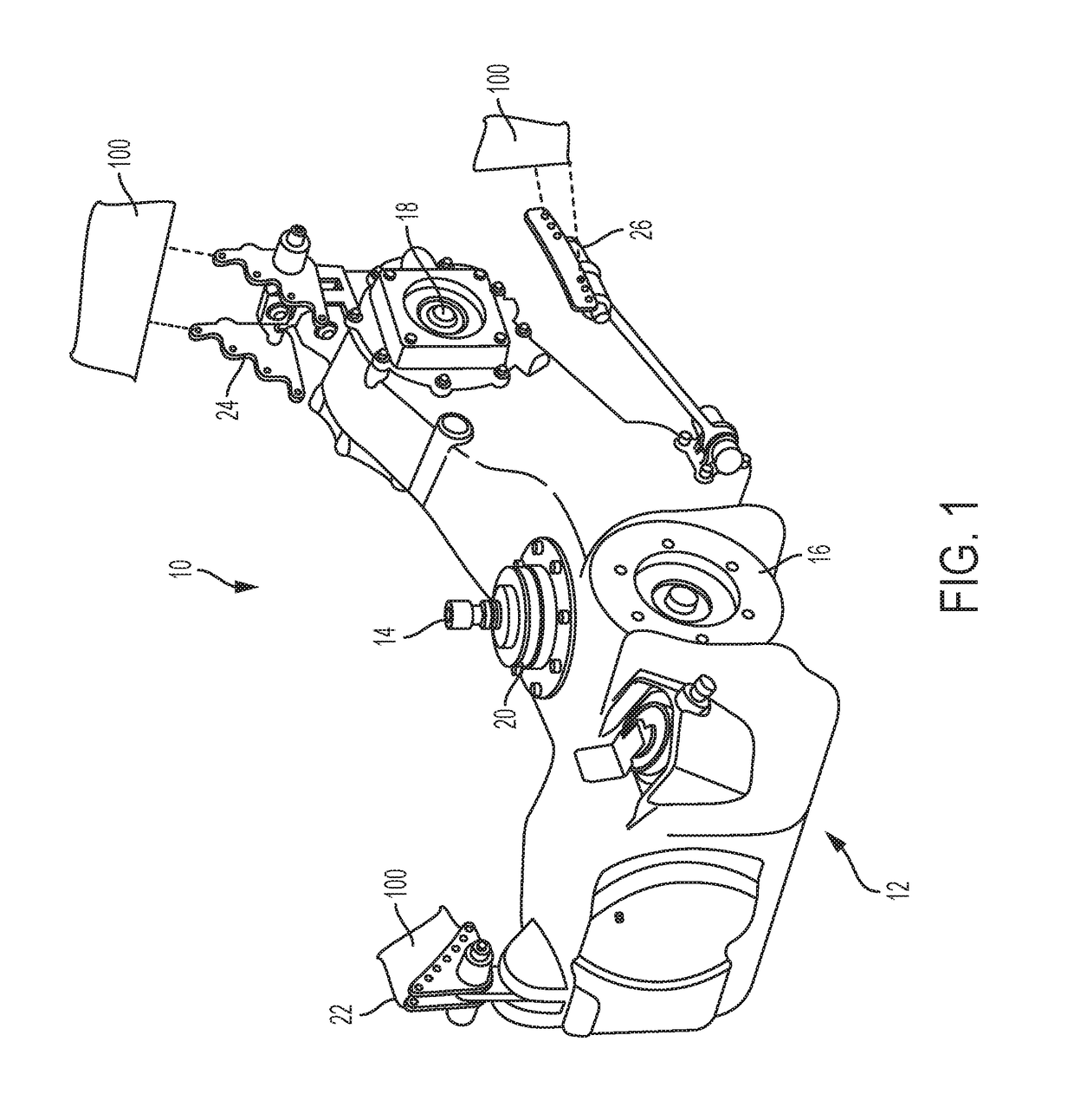
[0011]Referring to the drawings, FIG. 1 is a perspective view of a gearbox assembly 10, which includes a gearbox 12 and supporting elements sufficient to secure the gearbox 12 with respect to the engine 100. The engine 100 is depicted only schematically, and can, for example, be an aircraft gas turbine engine with a structural engine case, or another engine component to which the gearbox 12 is secured. The gearbox assembly 10 includes driveshaft connection 14, peripheral load connections 16 and 18, seal 20, and mounting links 22, 24, and 26. The gearbox 12 can, for example, be an auxiliary gearbox disposed to transmit torque from the engine 100 to a variety of peripheral loads not directly related to operation of the engine 100 or to propulsion (e.g. to a generator or air circulation system).

[0012]A driveshaft connection 14 attaches to a shaft of the engine 100 for torque transmission. The peripheral load connections 16 and 18 are two illustrative auxiliary driveshaft connection poi...


PUM


Abstract

A link assembly between an engine and a gearbox includes a male link coupled to the engine or the gearbox, a female link coupled to the engine or the gearbox, wherein the female link receives the male link to allow translation of the male link relative to the female link and to form a radial interface, wherein the radial interface dampens translation of the male link relative to the female link, and a pin releasably coupled to the male link and the female link to selectively retain the male link and the female link.

Description

BACKGROUND[0001]The present invention relates generally to support structures, and more particularly to a mounting link between an engine structure and an attached structure such as an auxiliary gearbox.[0002]Aircraft gas turbine auxiliary gearboxes are expected to withstand a variety of loads, from routine vibrational loads to sudden or extreme shocks caused by hard landings. The most extreme loads come from so-called “blade-off” events, when blades of the engine detach due to impacts or the like, causing severe shocks and often major damage to the working engines. Blade-off event loads are extremely unpredictable, but can be more than an order of magnitude stronger than any other sudden or extreme shock gas turbine engines are expected to experience, such as impacts due to hard landings. Extreme loads can cause damage to the gearbox itself, as well as to attached peripheral systems driven by the gearbox. In addition, extreme loads that damage or disconnect parts of the gearbox fro...

Claims


Application Information

Patent Timeline
Patent Type & Authority Applications(United States)
IPC IPC(8): F02C7/32F16F15/02F16H57/025
CPCF02C7/32F16H57/025F05D2260/30F05D2260/96F16F15/02F16F7/003F16F7/09F16F2230/24B64D2027/266F02C7/20
Inventor JIANG, YIWEIBLEWETT, MICHAEL R.
Owner HAMILTON SUNDSTRAND CORP
Why Eureka
Try Eureka