
Flow line analysis system and flow line display method

a flow line and flow analysis technology, applied in the field of flow line analysis system and flow, can solve the problems of insufficient protection of privacy of the person, inability to obtain accurate and difficulty in obtaining a wide heat map image indicating accurate staying information or passing information of a person (for example, a customer) in such a large store, so as to achieve easy and accurate recognition

Inactive Publication Date: 2017-11-16
PANASONIC I PRO SENSING SOLUTIONS CO LTD
View PDF8 Cites 6 Cited by
  • Summary
  • Abstract
  • Description
  • Claims
  • Application Information

AI Technical Summary

Benefits of technology

The present patent aims to provide a system and method for analyzing and displaying flow lines while protecting the privacy of people reflected in a wide imaging region. This enables easy and accurate recognition of a person's staying or passing information.

Problems solved by technology

When a heat map image is generated by superimposing staying information or passing information of a person on an image captured by a camera, if a layout in the store is changed, the staying information or passing information of the person obtained before the layout is changed does not match an image captured by the camera after the layout is changed, and thus an accurate heat map image indicating accurate staying information or passing information cannot be obtained.
In addition, in NPL 1, since an image as a base of the heat map image is the image captured by the camera, the person is shown in the image, and thus there is a problem in that the privacy of the person is not appropriately protected.
In a large store or the like, a plurality of cameras are frequently required to monitor situations in a store, but, in the configuration disclosed in PTL 1 or NPL 1, it is difficult to obtain a wide heat map image indicating accurate staying information or passing information of a person (for example, a customer) in such a large store or the like.

Method used


Image

  • Flow line analysis system and flow line display method
  • Flow line analysis system and flow line display method
  • Flow line analysis system and flow line display method

Examples


modification example

of Present Exemplary Embodiment

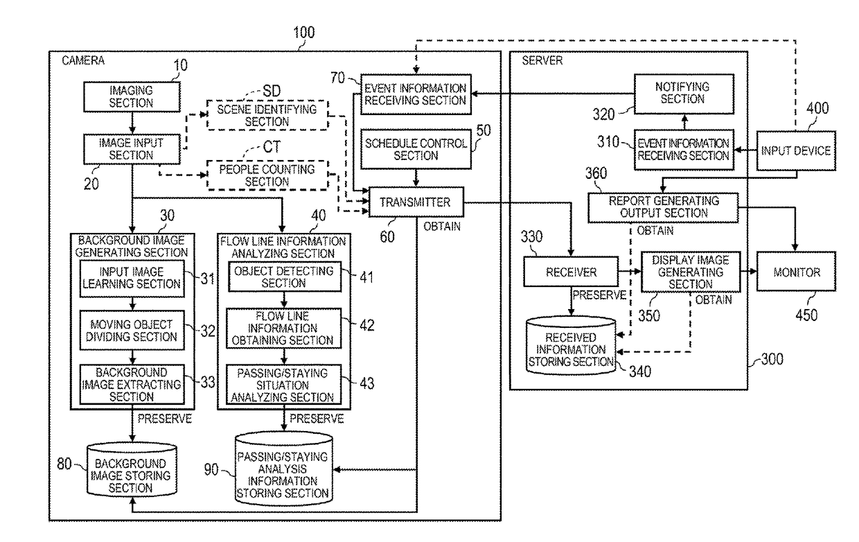
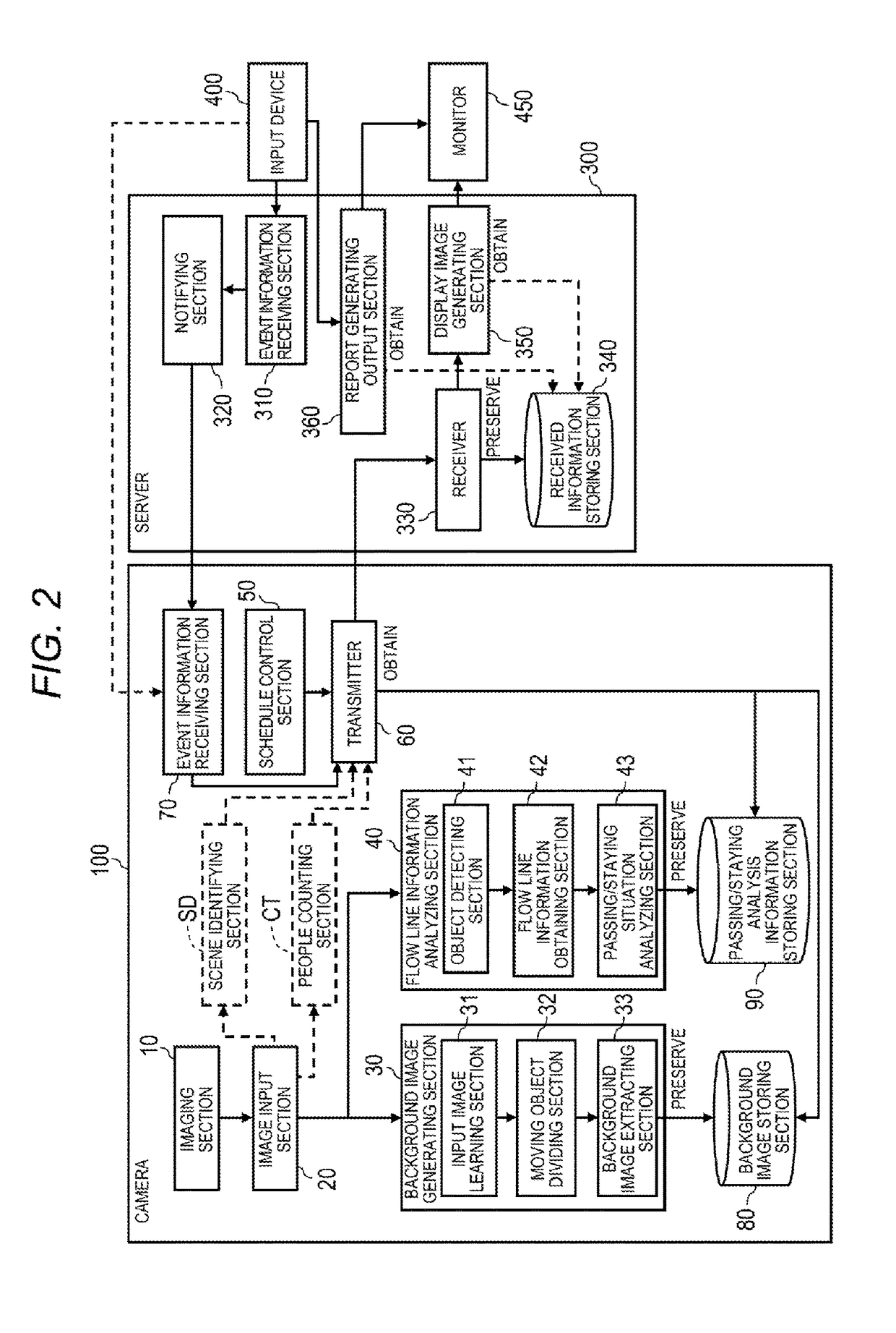
[0119]In the above-described present exemplary embodiment, the process of generating a flow line analysis image is performed by server 300, but the process of generating a flow line analysis image may also be performed by camera 100 (refer to FIG. 13). FIG. 13 is a block diagram illustrating details of a functional internal configuration of camera 100S of a modification example of the present exemplary embodiment. Camera 100S illustrated in FIG. 13 includes imaging section 10, image input section 20, background image generating section 30, flow line information analyzing section 40, schedule control section 50, transmitter 60S, event information receiving section 70, background image storing section 80, passing / staying analysis information storing section 90, and display image generating section 350S. In description of each section of camera 100S illustrated in FIG. 13, constituent elements having the same configuration and operation as those of camera...


PUM


Abstract

Displayed is a flow line analysis image in which the privacy of a person reflected in a wide imaging region is appropriately protected, and staying information or passing information of a person in the wide imaging region can be easily and accurately recognized. A camera includes an imaging section that captures an image of a differing imaging region for each camera, a background image generating section that repeatedly generates a background image of a captured image of the imaging region at predetermined timings, a flow line information analyzing section that extracts flow line information regarding a staying position or a passing position of a moving object in the imaging region of the camera, included in the captured image, and a transmitter that transmits the background image and the flow line information of the moving object to a server at a predetermined transmission cycle. A server includes an image generating section that acquires flow line analysis images based on superimposition between the background image of the captured image and the flow line information of the moving object for each camera, and generates a wide-region flow line analysis image by using the plurality of acquired flow line analysis images, and a display control section that displays the wide-region flow line analysis image on a display section.

Description

TECHNICAL FIELD[0001]The present disclosure relates to a flow line analysis system, and a flow line display method capable of displaying a flow line analysis image in which staying information or passing information of a person is superimposed on an image captured by a camera.BACKGROUND ART[0002]As the related art in which a level of activity of a person over a period of time at an imaging site where a camera is provided is displayed as a heat map image, for example, PTL 1 is known.[0003]PTL 1 discloses a technique of analyzing a flow line of a person at the imaging site where a security camera connected to a network is provided so as to calculate a level of activity, generating a heat map image in which a detection result from a sensor is superimposed on a floor plan of the imaging site, and displaying the heat map image on a browser screen corresponding to the security camera. Consequently, it is possible to understand a level of activity of the person at the imaging site by viewi...

Claims


Application Information

Patent Timeline
Patent Type & Authority Applications(United States)
IPC IPC(8): G08B13/196G06F17/30G06T7/292
CPCG08B13/19645G06T7/292G06F17/30244G08B13/19604G08B13/19656G08B13/19682G08B13/19686H04N7/181G06F16/50
Inventor TAKAHASHI, HIDEAKITAYAMA, TETSUOOGUCHI, TAKAEHAGISU, SHINPEI
Owner PANASONIC I PRO SENSING SOLUTIONS CO LTD
Learn More