System and method for concurrent odometry and mapping

a technology of odometry and mapping, applied in the field of image capture and processing, can solve the problems of limiting the utility and effectiveness of machine vision techniques, significant amount of time and resources,

a technology of odometry and mapping, applied in the field of image capture and processing, can solve the problems of limiting the utility and effectiveness of machine vision techniques, significant amount of time and resources,

US20170336511A1Active Publication Date: 2017-11-23GOOGLE LLC

Image

  • System and method for concurrent odometry and mapping
  • System and method for concurrent odometry and mapping
  • System and method for concurrent odometry and mapping

Examples


Embodiment Construction

[0011]The following description is intended to convey a thorough understanding of the present disclosure by providing a number of specific embodiments and details involving the determination of a relative position or relative orientation of an electronic device based on image-based identification of objects in a local environment of the electronic device. It is understood, however, that the present disclosure is not limited to these specific embodiments and details, which are examples only, and the scope of the disclosure is accordingly intended to be limited only by the following claims and equivalents thereof. It is further understood that one possessing ordinary skill in the art, in light of known systems and methods, would appreciate the use of the disclosure for its intended purposes and benefits in any number of alternative embodiments, depending upon specific design and other needs.

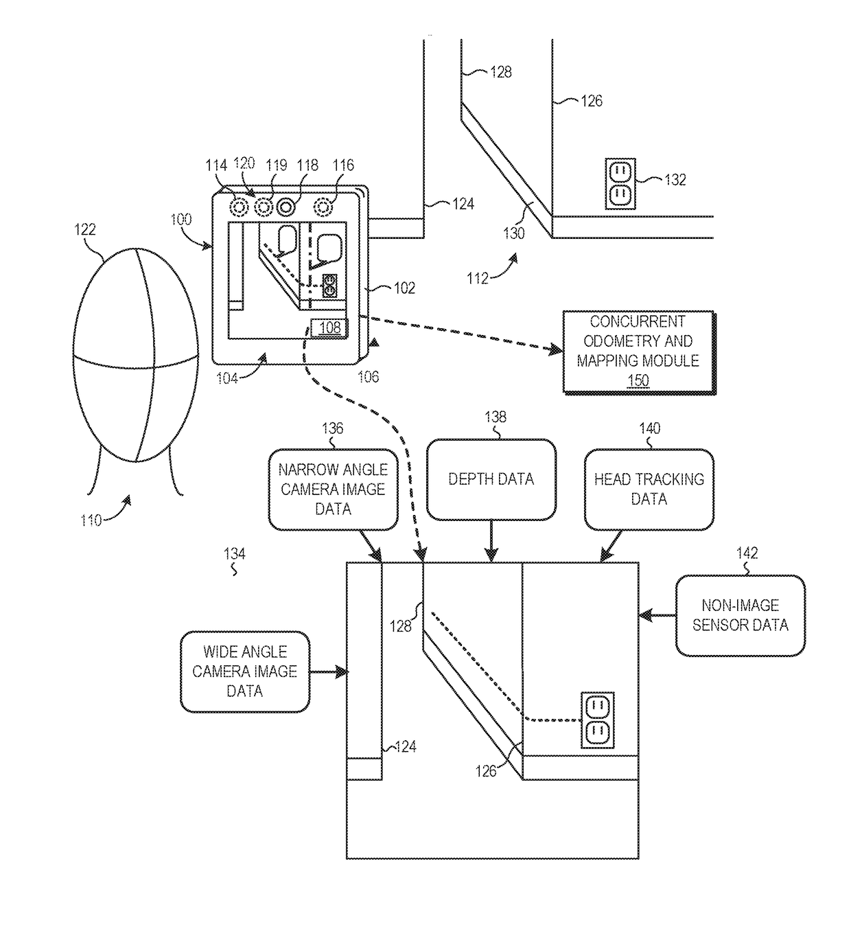
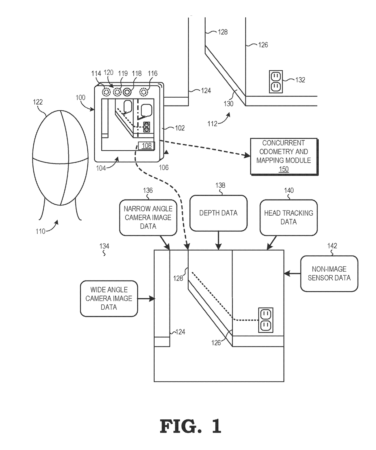
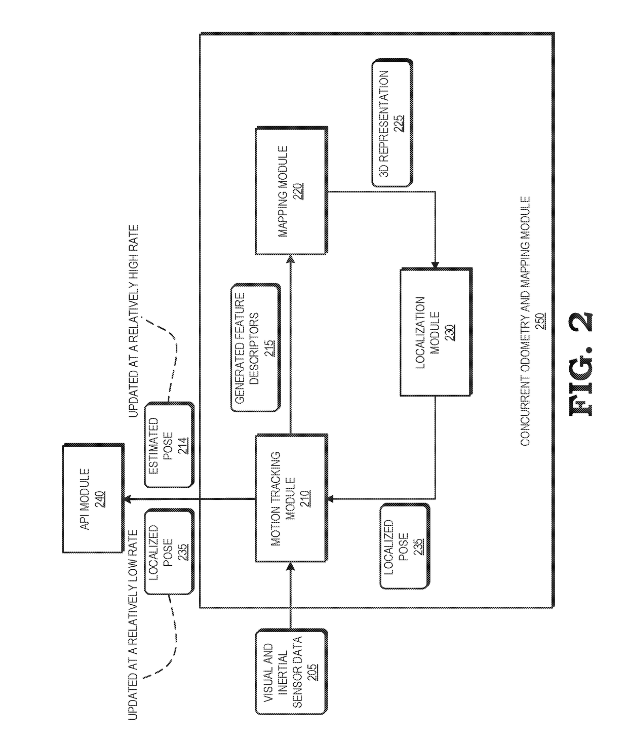
[0012]FIGS. 1-6 illustrate various techniques for tracking motion of an electronic device in an...


PUM


Abstract

An electronic device tracks its motion in an environment while building a three-dimensional visual representation of the environment that is used to correct drift in the tracked motion. A motion tracking module estimates poses of the electronic device based on feature descriptors corresponding to the visual appearance of spatial features of objects in the environment. A mapping module builds a three-dimensional visual representation of the environment based on a stored plurality of maps, and feature descriptors and estimated device poses received from the motion tracking module. The mapping module provides the three-dimensional visual representation of the environment to a localization module, which identifies correspondences between stored and observed feature descriptors. The localization module performs a loop closure by minimizing the discrepancies between matching feature descriptors to compute a localized pose. The localized pose corrects drift in the estimated pose generated by the motion tracking module.

Description

CROSS-REFERENCE TO RELATED APPLICATIONS[0001]The present application is related to and claims priority to the following co-pending application, the entirety of which is incorporated by reference herein: U.S. Provisional Patent Application Ser. No. 62 / 337,987 (Attorney Docket No. 1500-G16013), entitled “Methods and Systems for VR / AR Functionality in a Portable Device.”BACKGROUNDField of the Disclosure[0002]The present disclosure relates generally to imagery capture and processing and more particularly to machine vision using captured imagery.Description of the Related Art[0003]Machine vision and display techniques, such as simultaneous localization and mapping (SLAM), visual inertial odometry (VIO), area learning applications, augmented reality (AR), and virtual reality (VR), often rely on the identification of objects within the local environment of a device through the analysis of imagery of the local environment captured by the device. To support these techniques, the device navig...

Claims


Application Information

Patent Timeline
23 Nov 2017
Publication
US20170336511A1
IPC
G01S17/89; H04N13/02; G06T7/55; G01S7/481; H04N13/00
CPC
G01S17/89; G06T7/55; H04N13/0271; G01S7/4817; H04N13/0242; H04N13/0214; H04N13/004; G06T2207/10012
Inventors
NERURKAR, ESHA; LYNEN, SIMON