Optical imaging lens, image capturing apparatus and electronic device

an image capturing apparatus and optical imaging technology, applied in the field of optical imaging lenses and image capturing apparatuses, can solve the problems of insufficient imaging range, inability to meet the requirements of miniaturization, and limited view angles of miniaturized imaging systems that are currently availabl

Active Publication Date: 2017-11-23
LARGAN PRECISION
View PDF2 Cites 39 Cited by
  • Summary
  • Abstract
  • Description
  • Claims
  • Application Information

AI Technical Summary

Benefits of technology

[0005]According to one aspect of the present disclosure, an optical imaging lens, comprising, in order from an object side to an image side: a first lens element with positive refractive power having an image-side surface being convex in a paraxial region thereof; a second lens element; a third lens element having positive refractive power; a fourth lens element; a fifth lens element with positive refractive power having an object-side surface being concave in a paraxial region thereof, an image-side surface being convex in a paraxial region thereof, and both the object-side surface and the image-side surface being aspheric; and a sixth lens element having an image-side surface being concave in a

Problems solved by technology

The view angles of the miniaturized imaging systems that are currently available are too limited and do not have sufficient imaging range.
Meanwhile, most conventional lens assemblies wit

Method used


Image

  • Optical imaging lens, image capturing apparatus and electronic device
  • Optical imaging lens, image capturing apparatus and electronic device
  • Optical imaging lens, image capturing apparatus and electronic device

Examples


1st embodiment

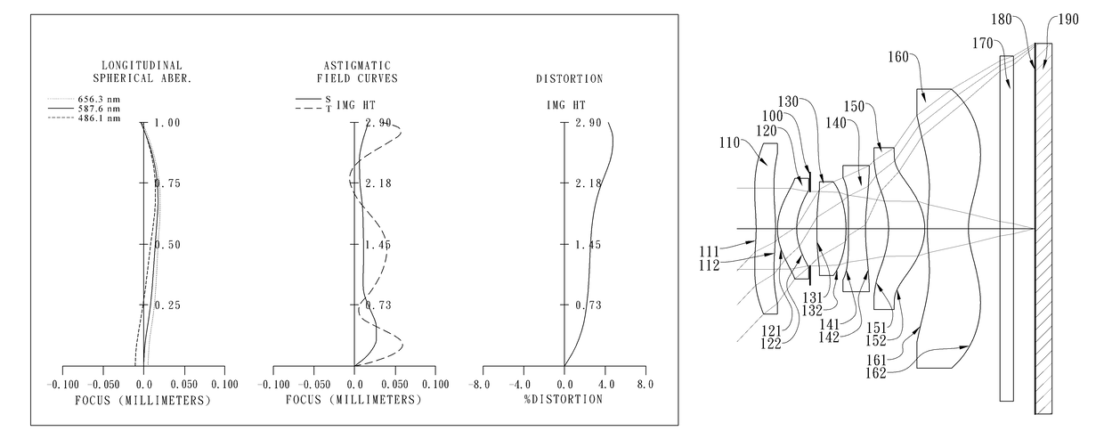
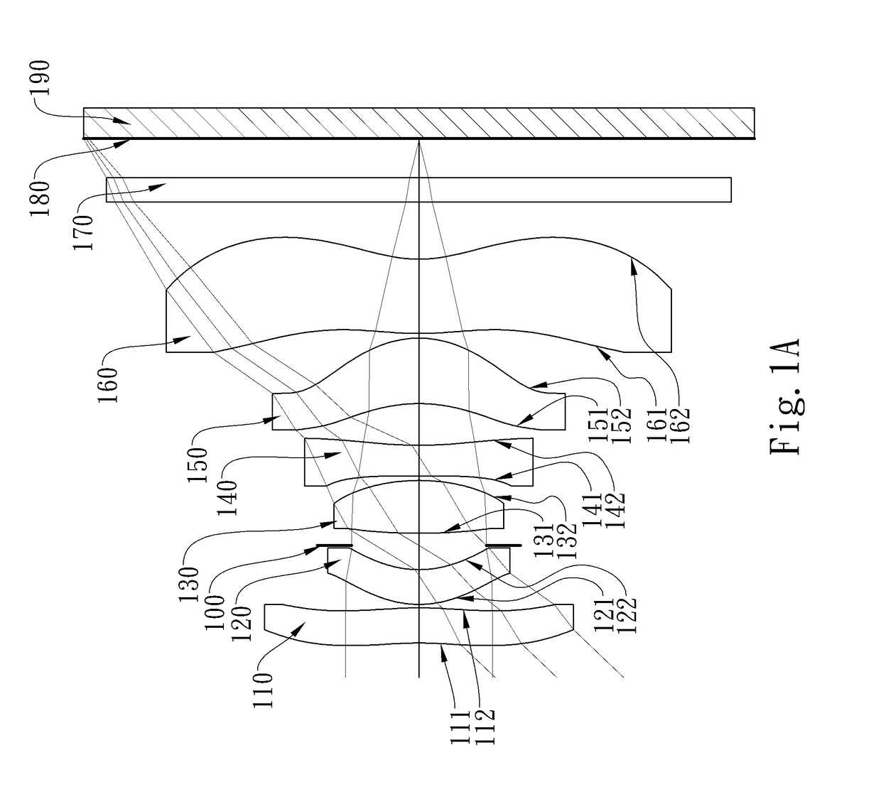
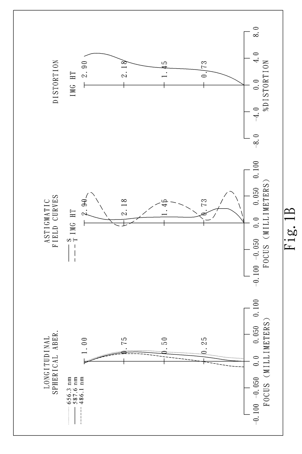
[0063]FIG. 1A is a schematic view of an image capturing apparatus according to the 1st embodiment of the present disclosure. FIG. 1B shows, in order from left to right, longitudinal spherical aberration curves, astigmatic field curves and a distortion curve of the image capturing apparatus according to the 1st embodiment.

[0064]In FIG. 1A, the image capturing apparatus includes an optical imaging lens (not otherwise herein labeled) of the present disclosure and an image sensor 190. The optical imaging lens includes, in order from an object side to an image side, a first lens element 110, a second lens element 120, an aperture stop 100, a third lens element 130, a fourth lens element 140, a fifth lens element 150 and a sixth lens element 160.

[0065]The first lens element 110 with positive refractive power has an object-side surface 111 being concave in a paraxial region thereof, an image-side surface 112 being convex in a paraxial region thereof, both the object-side surface 111 and th...

2nd embodiment

[0097]FIG. 2A is a schematic view of an image capturing apparatus according to the 2nd embodiment of the present disclosure. FIG. 2B shows, in order from left to right, longitudinal spherical aberration curves, astigmatic field curves and a distortion curve of the image capturing apparatus according to the 2nd embodiment.

[0098]In FIG. 2A, the image capturing apparatus includes an optical imaging lens (not otherwise herein labeled) of the present disclosure and an image sensor 290. The optical imaging lens includes, in order from an object side to an image side, a first lens element 210, a second lens element 220, an aperture stop 200, a third lens element 230, a fourth lens element 240, a fifth lens element 250 and a sixth lens element 260.

[0099]The first lens element 210 with positive refractive power has an object-side surface 211 being concave in a paraxial region thereof, an image-side surface 212 being convex in a paraxial region thereof, both the object-side surface 211 and th...

3rd embodiment

[0109]FIG. 3A is a schematic view of an image capturing apparatus according to the 3rd embodiment of the present disclosure. FIG. 3B shows, in order from left to right, longitudinal spherical aberration curves, astigmatic field curves and a distortion curve of the image capturing apparatus according to the 3rd embodiment.

[0110]In FIG. 3A, the image capturing apparatus includes an optical imaging lens (not otherwise herein labeled) of the present disclosure and an image sensor 390. The optical imaging lens includes, in order from an object side to an image side, a first lens element 310, a second lens element 320, an aperture stop 300, a third lens element 330, a fourth lens element 340, a fifth lens element 350 and a sixth lens element 360.

[0111]The first lens element 310 with positive refractive power has an object-side surface 311 being convex in a paraxial region thereof, an image-side surface 312 being convex in a paraxial region thereof, both the object-side surface 311 and the...


PUM

PropertyMeasurementUnit
Volumeaaaaaaaaaa
Volumeaaaaaaaaaa
Volumeaaaaaaaaaa

Abstract

The present disclosure provides an optical imaging lens, comprising, in order from an object side to an image side: a first lens element with positive refractive power having an image-side surface being convex in a paraxial region thereof; a second lens element; a third lens element having positive refractive power; a fourth lens element; a fifth lens element with positive refractive power having an object-side surface being concave in a paraxial region thereof, an image-side surface being convex in a paraxial region thereof, and both the object-side surface and the image-side surface being aspheric; and a sixth lens element having an image-side surface being concave in a paraxial region thereof, at least one convex shape in an off-axial region on the image-side surface, and both an object-side surface and the image-side surface being aspheric. There are a total of six lens elements.

Description

RELATED APPLICATIONS[0001]This application claims priority to Taiwan Application Serial Number 105115692, filed on May 20, 2016, which is incorporated by reference herein in its entirety.BACKGROUNDTechnical Field[0002]The present disclosure relates to an optical imaging lens and an image capturing apparatus, and more particularly, to an optical imaging lens and an image capturing apparatus applicable to electronic devices.Description of Related Art[0003]As the technology advances rapidly, our lifestyles have become more multifaceted than ever before. In order to enable abundant user experiences, camera modules are widely utilized. In addition to the mobile devices such as smartphones and tablets, the applications of the camera modules for various intelligent electronics, car devices and intelligent home systems, such as optical recognition devices, rear view cameras, driving cameras, sports cameras or drone cameras, have become a trend of the technology development.[0004]Recently, m...

Claims


Application Information

Patent Timeline
IPC IPC(8): G02B13/00G02B5/20G02B5/00G02B9/62G02B1/04
CPCG02B13/0045G02B5/208G02B5/005G02B1/04G02B9/62G02B13/06
Inventor CHEN, CHUN-YENCHEN, WEI-YU
Owner LARGAN PRECISION
Why Eureka
Try Eureka