
Liquid crystal composition and liquid crystal display device

a liquid crystal display and composition technology, applied in liquid crystal compositions, instruments, chemistry apparatuses and processes, etc., can solve the problems of small electric power consumption, large contrast ratio of devices, long service life of devices, etc., and achieve large optical anisotropy and high stability to ultraviolet light

Active Publication Date: 2017-12-21
JNC CORP +1
View PDF4 Cites 10 Cited by
  • Summary
  • Abstract
  • Description
  • Claims
  • Application Information

AI Technical Summary

Benefits of technology

The invention provides a liquid crystal composition with specific characteristics such as high maximum temperature, low minimum temperature, large optical anisotropy, large positive dielectric anisotropy, and high stability to ultraviolet light. Additionally, the composition can have a suitable balance between at least two of these characteristics. This liquid crystal composition can be used in liquid crystal display devices and also in 3D lenses.

Problems solved by technology

Large dielectric anisotropy in the composition contributes to low threshold voltage, small electric power consumption and a large contrast ratio in the device.
In the case where such stability is high, the device has a long service life.

Method used


Image

  • Liquid crystal composition and liquid crystal display device
  • Liquid crystal composition and liquid crystal display device
  • Liquid crystal composition and liquid crystal display device

Examples


example 1

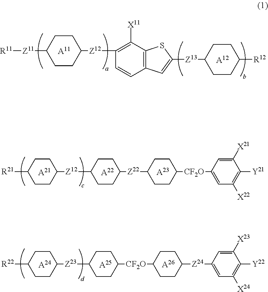
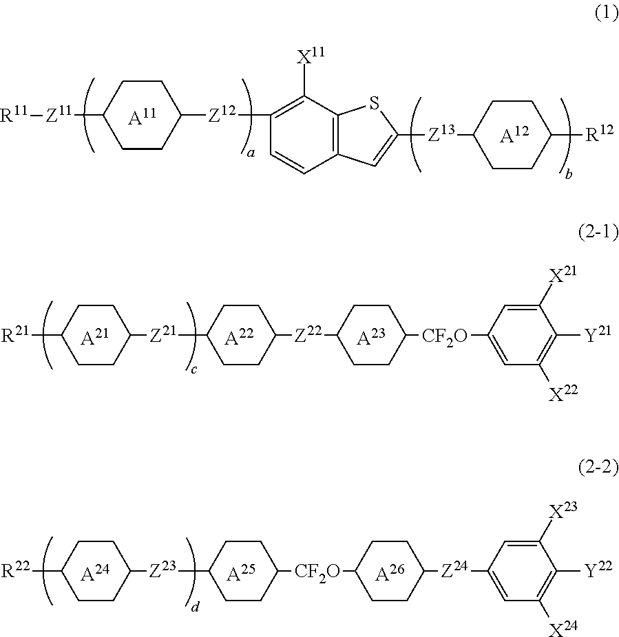
[0118]A liquid crystal composition was prepared by changing part of the compound represented by formula (4) in Comparative Example 1 to a compound being an essential component of the invention represented by formula (1).

3-btB(2F)B-3(1-7)10% 3-BB(F,F)XB(F,F)-F(2-1-2)9%3-BB(F)B(F,F)XB(F)-F(2-1-7)3%3-BB(F)B(F,F)XB(F,F)-F(2-1-8)2%4-BB(F)B(F,F)XB(F,F)-F(2-1-8)7%5-BB(F)B(F,F)XB(F,F)-F(2-1-8)7%3-BB(F,F)XB(F)B(F,F)-F(2-2-1)6%3-BB(F)B(F,F)-F(3-8)3%2-BTB-O1(4-3)6.2% 3-BTB-O1(4-3)6.2% 4-BTB-O1(4-3)6.2% 4-BTB-O2(4-3)6.2% 5-BTB-O1(4-3)6.2% 3-H2BTB-2(4-10)4%3-H2BTB-3(4-10)3%3-HB(F)TB-2(4-11)5%3-HB(F)TB-3(4-11)5%3-HB(F)TB-4(4-11)5%NI = 93.7° C.; Tc

[0119]A liquid crystal composition having high NI, large Δn, large Δ∈ and small Vth was able to be prepared by changing part of the compound represented by formula (4) in Comparative Example 1 to a compound being an essential component of the invention represented by formula (1).

example 2

[0120]

2O-btB(2F)B-3(1-7)10% 3-BB(F,F)XB(F,F)-F(2-1-2)9%3-BB(F)B(F,F)XB(F)-F(2-1-7)3%3-BB(F)B(F,F)XB(F,F)-F(2-1-8)2%4-BB(F)B(F,F)XB(F,F)-F(2-1-8)7%5-BB(F)B(F,F)XB(F,F)-F(2-1-8)7%3-BB(F,F)XB(F)B(F,F)-F(2-2-1)6%3-BB(F)B(F,F)-F(3-8)3%2-BTB-O1(4-3)8.4% 3-BTB-O1(4-3)8.4% 4-BTB-O1(4-3)8.4% 4-BTB-O2(4-3)8.4% 5-BTB-O1(4-3)8.4% 3-HB(F)TB-2(4-11)5%3-HB(F)TB-3(4-11)3%3-HB(F)TB-4(4-11)3%NI = 95.3° C.; Tc

example 3

[0121]

2O-bt(7F)B(2F)B-O4(1-8)10% 3-BB(F,F)XB(F,F)-F(2-1-2)9%3-BB(F)B(F,F)XB(F)-F(2-1-7)3%3-BB(F)B(F,F)XB(F,F)-F(2-1-8)2%4-BB(F)B(F,F)XB(F,F)-F(2-1-8)7%5-BB(F)B(F,F)XB(F,F)-F(2-1-8)7%3-BB(F,F)XB(F)B(F,F)-F(2-2-1)6%3-BB(F)B(F,F)-F(3-8)3%2-BTB-O1(4-3)8.6% 3-BTB-O1(4-3)8.6% 4-BTB-O1(4-3)8.6% 4-BTB-O2(4-3)8.6% 5-BTB-O1(4-3)8.6% 3-HB(F)TB-2(4-11)5%3-HB(F)TB-3(4-11)5%NI = 94.8° C.; Tc


PUM


Abstract

Shown is a liquid crystal composition satisfying at least one or having suitable balance regarding at least two of characteristics such as high maximum or low minimum temperature of a nematic phase, large optical anisotropy, large positive dielectric anisotropy and high stability to ultraviolet light, a liquid crystal display device including such a composition, particularly including an encapsulated composition, and a liquid crystal display device including the composition serving as a constituent of 3D lens. The liquid crystal composition contains a specific compound having large optical anisotropy as a first component, and a specific compound having large optical anisotropy and positive dielectric anisotropy as a second component; a specific compound having large positive dielectric anisotropy as a third component; and a specific compound having large optical anisotropy and further having high maximum or low minimum temperature as a fourth component, and the liquid crystal display device includes the composition.

Description

CROSS-REFERENCE TO RELATED APPLICATION[0001]This application claims the priority benefit of Japan application serial no. 2016-118984, filed on Jun. 15, 2016. The entirety of the above-mentioned patent application is hereby incorporated by reference herein and made a part of this specification.TECHNICAL FIELD[0002]The invention relates to a liquid crystal composition, a liquid crystal display device including the composition, and so forth. In particular, the invention relates to a liquid crystal composition having large optical anisotropy and large positive dielectric anisotropy, and a device including the composition.BACKGROUND ART[0003]In a liquid crystal display device, a classification based on an operating mode for liquid crystal molecules includes a phase change (PC) mode, a twisted nematic (TN) mode, a super twisted nematic (STN) mode, an electrically controlled birefringence (ECB) mode, an optically compensated bend (OCB) mode, an in-plane switching (IPS) mode, a vertical ali...

Claims


Application Information

Patent Timeline
IPC IPC(8): C09K19/34G02F1/29
CPCG02F1/29C09K19/3491C09K19/20C09K19/3066C09K2019/0466C09K2019/123C09K2019/181C09K2019/3019C09K2019/304C09K2019/3422
Inventor OKABE, EIJI
Owner JNC CORP
Learn More