Radial Scissor Lift Table and Method

a technology of radial scissors and lift tables, which is applied in the field of tables and methods, can solve the problems of difficult to achieve telescoping designs, require complicated coupling brackets, and undesirable surface mounting of tracks, links or brackets

Active Publication Date: 2017-12-28
WITT MARC STEFAN
View PDF0 Cites 0 Cited by
  • Summary
  • Abstract
  • Description
  • Claims
  • Application Information

AI Technical Summary

Benefits of technology

The present invention provides a scissor lift assembly for raising and lowering an unattached table top. The assembly has at least three scissor mechanisms mounted in a polar array, with lower and upper support members each having at least three radially disposed protruding lugs. Each scissor assembly includes a table-scissor member and a floor-scissor member, each with a pivotally connected lug. An actuator assembly is coupled to the lower and upper support members for moving the scissor assemblies. The scissor assemblies have a radial scissor axis which crosses the actuator axis, and each scissor assembly includes a table-scissor member and a floor-scissor member for supporting and moving the table top. The invention also provides a method for raising a table top using the scissor lift assembly. The technical effects of the invention include improved stability and flexibility in raising and lowering table tops, as well as reduced noise and vibration during operation.

Problems solved by technology

This is difficult to accomplish with a telescoping design, because telescopes have inherent limits of motion.
Conventional industrial scissor lifting mechanisms are available, but require complicated coupling brackets to confine the travelling table-top surface to a coaxial position with a vertical axis.
Drill holes in the table surface, to mount tracks, links or brackets to the surface are undesirable, especially if the table is made of glass or stone.
Furthermore, fasteners that penetrate the table top, damage the top working surface, and reduce the usefulness of the table

Method used


Image

  • Radial Scissor Lift Table and Method
  • Radial Scissor Lift Table and Method
  • Radial Scissor Lift Table and Method

Examples


Embodiment Construction

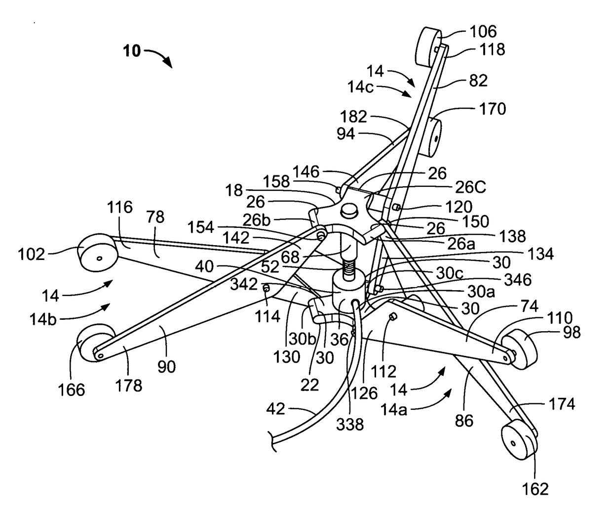
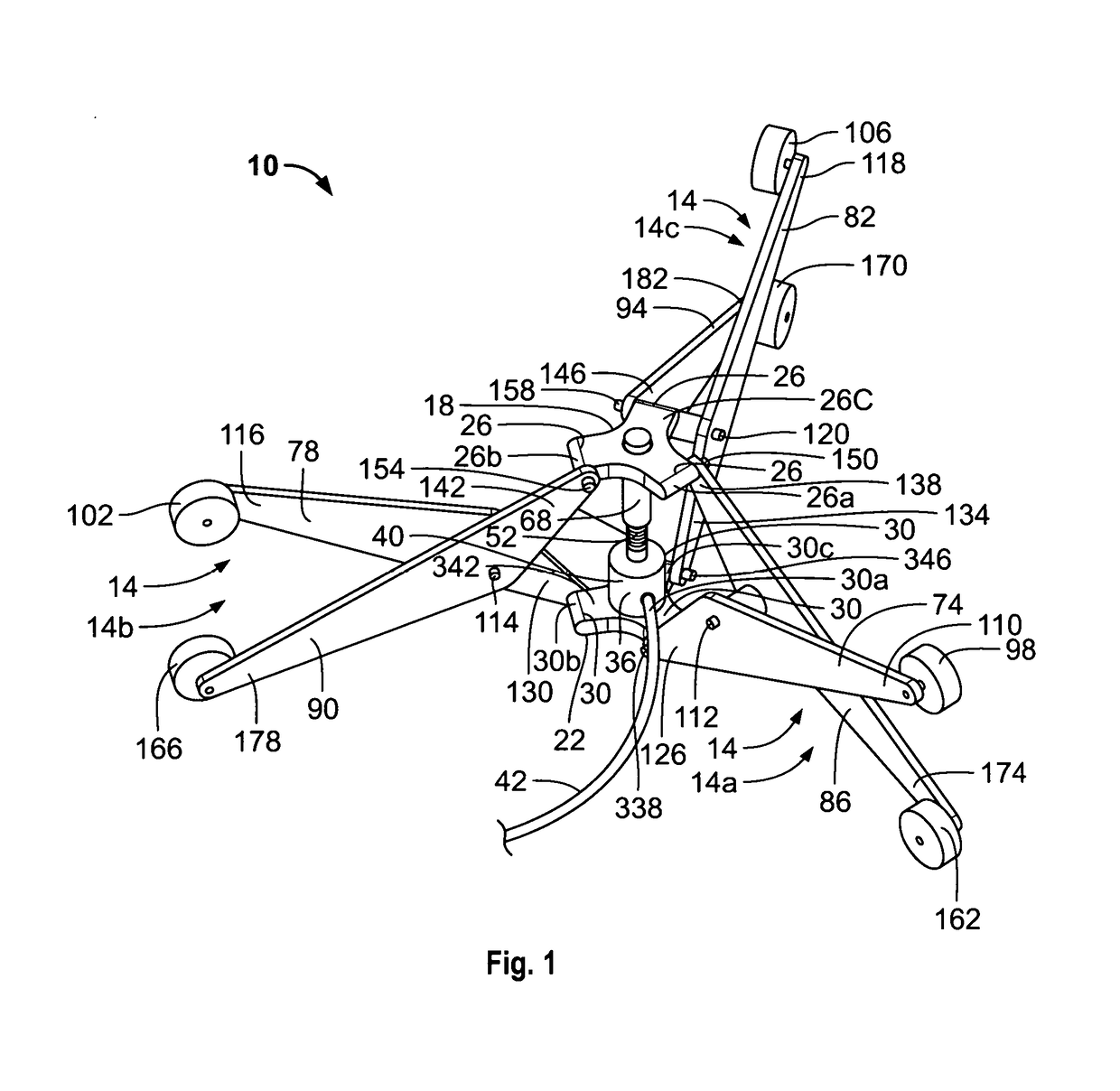
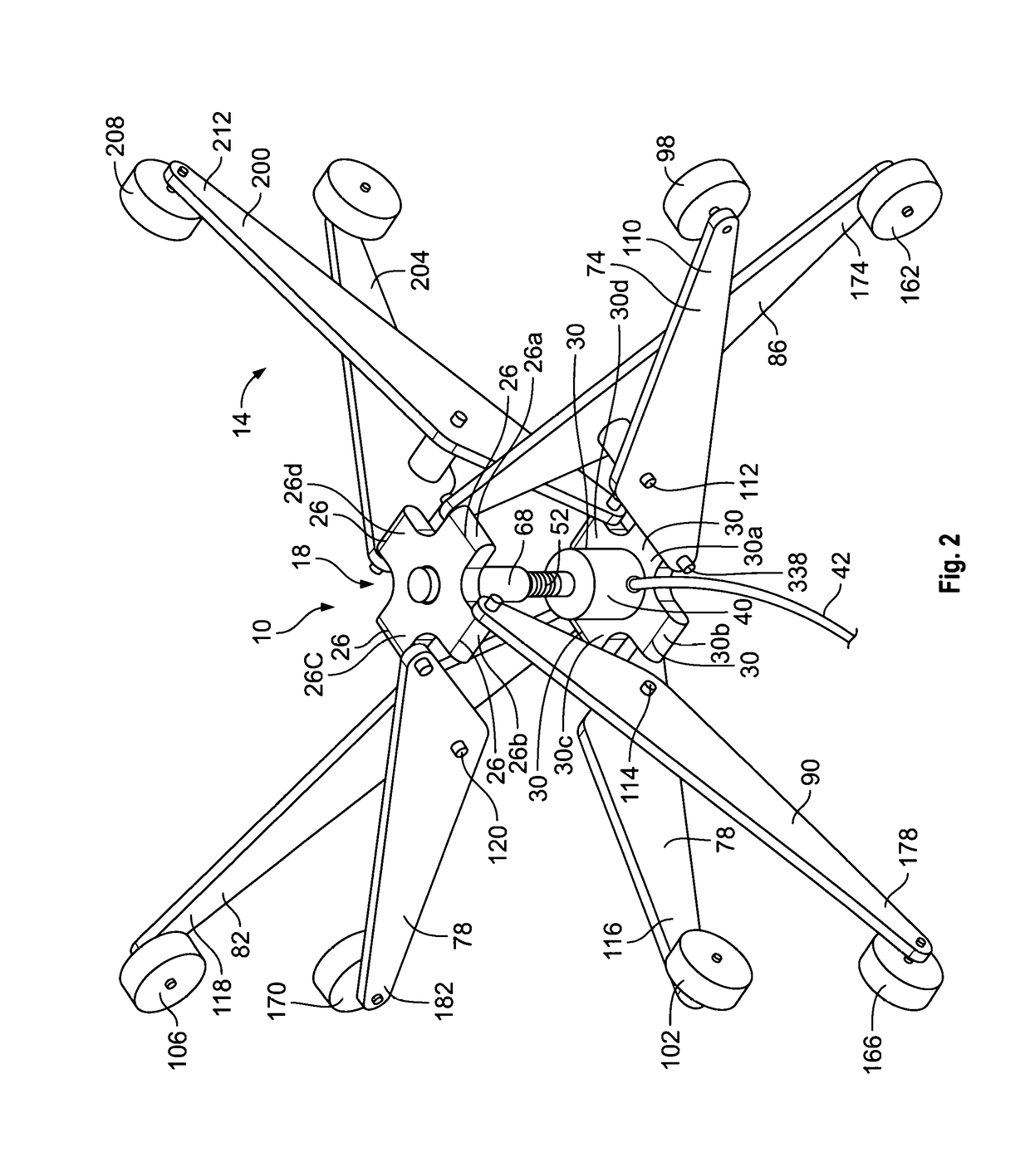
[0006]Embodiments of the present invention provide a scissor lift assembly for raising and lowering an unattached table top. The scissor lift assembly has at least (3) scissor mechanisms mounted in a polar array. The assembly has lower and upper support members; each having at least three radially disposed protruding lugs. The scissor lift assembly also has at least three scissor assemblies coupled to the upper and lower support members in a polar array. Each scissor assembly comprises a table-scissor member having a lower end pivotally connected to one of the lugs of the lower support member and an upper end which supports a rotatable table wheel. Each scissor assembly further comprises a floor-scissor member pivotally connected to the table scissor member and having an upper end pivotally connected to one of the lugs of the upper support member and a lower end which supports a rotatable floor wheel. An actuator assembly is coupled to the lower and upper support members for moving ...


PUM


Abstract

A radial-scissor lift assembly for a table top comprising an upper support member, a lower support member, and at least three scissor assemblies coupled to the upper and lower support members. Each scissor assembly includes a table-scissor member rotatably supporting a table wheel adapted for contacting an unattached table. Each scissor assembly further includes a floor-scissor member rotatably supporting a floor wheel adapted for contacting a surface supporting the radial-scissor lift assembly. The radial-scissor lift assembly has an actuator assembly coupled to the lower support member and to the upper support member for moving the scissor assemblies. A method for lowering a table top comprising disposing a table top on at least three table rollers, and rolling the table rollers along the bottom on the table top and away from the center of the table top to cause the table top to be lowered.

Description

[0001]This is a continuation-in-part patent application of co-pending patent application having application Ser. No. 14 / 998,932, filed Mar. 7, 2016. Benefit of the Mar. 7, 2016 filing date is claimed.BACKGROUND OF THE INVENTION1. Field of Invention[0002]The present invention broadly relates in general to a table and method. More specifically, embodiments of the present invention provide a radial-scissor lift table having a movable top. More specifically further, embodiments of the present invention relate to a method for moving an unattached table top with scissor lift assemblies that are coupled to an actuator assembly which provides the requisite dynamic forces for elevating and lowering the unattached table top relative to a surface that supports the scissor lift assemblies, such as a floor.2. Description of the Background Art[0003]A table with movable or adjustable height table top employs a mechanism to raise or lower the table top, which is ideal for compact homes, office work...

Claims


Application Information

Patent Timeline
Patent Type & Authority Applications(United States)
IPC IPC(8): A47B9/16A47B13/00A47B13/02B66F7/06
CPCA47B9/16B66F7/0658A47B13/003A47B13/02A47B2013/026A47B9/04A47B13/023A47B2200/005
Inventor WITT, MARC STEFAN
Owner WITT MARC STEFAN
Why Eureka
Try Eureka