
Dry-fire bypass for a fastening tool

Active Publication Date: 2018-01-04
BLACK & DECKER INC
View PDF3 Cites 4 Cited by
  • Summary
  • Abstract
  • Description
  • Claims
  • Application Information

AI Technical Summary

Benefits of technology

The present invention relates to a fastening tool with a contact trip that can be moved to bypass a fastener drive system arming device. A coil spring is used to absorb or take up the force that the contact trip would normally apply on the arming device, thereby limiting the force to protect the contact trip switch from damage and ensure its durability during use. Another benefit of the bypass system is that it allows the contact trip to be placed in the fastening tool housing, acting as a hard stop to absorb the shock and protect the contact trip from damage. Additionally, the invention also includes a biasing agent or force take-up member that can act in response to a minimum quantity of fasteners in the magazine to engage the switch lever and activate the tool.

Problems solved by technology

However, if the supply of fasteners in the magazine becomes exhausted or “dry” when the fastening tool is fired, the driver of the drive system encounters no resistance as the driver is fired along the drive track, until the driver ultimately engages some other portion of the fastening tool, or even the work surface via the contact trip.
This condition is called a “dry-fire”, and is highly destructive to fastening tool mechanisms.
To date, conventional attempts to solve the problem have been unsatisfactory for several reasons.
One reason is that many conventional dry-fire avoidance systems freeze a lower contact trip so that the lower contact trip is unable to move even if the lower contact trip is thrust against a work surface, an event which places additional stresses on the contact trip system.
However, the vulnerability of conventional contact trip systems to being slammed or dropped significantly reduces the lifetimes of conventional arming devices.
Still another reason why conventional dry-fire avoidance systems have proven unsatisfactory is that, in electrically-driven fastening tools, the fastener drive system arming device often includes a relatively fragile contact trip switch, which is closed by a linkage actuated by the contact trip when the contact trip moves to the firing position.
However, conventional fastening tools include no systems for limiting the force exerted upon the contact trip switch when the contact trip is shoved against a work surface, even during normal operating conditions when the magazine is loaded with fasteners.
The problems enumerated above still exist in fastener drive system arming devices connected mechanically or otherwise to other types of fastener-driving systems, such as pneumatic, explosive-gas, or hydraulic.
Consequently, existing fastening tools are vulnerable both to dry-fire conditions and to shocks caused by the operator slamming the tool against a work surface, or dropping the tool nose-first onto an unyielding surface, like concrete.

Method used


Image

  • Dry-fire bypass for a fastening tool
  • Dry-fire bypass for a fastening tool
  • Dry-fire bypass for a fastening tool

Examples


Embodiment Construction

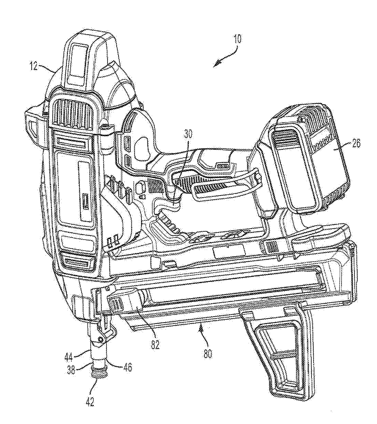
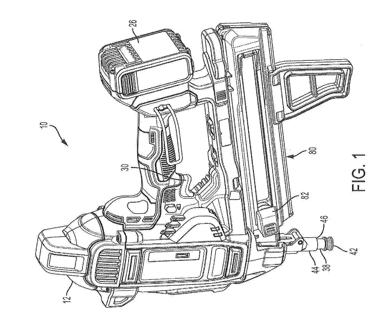
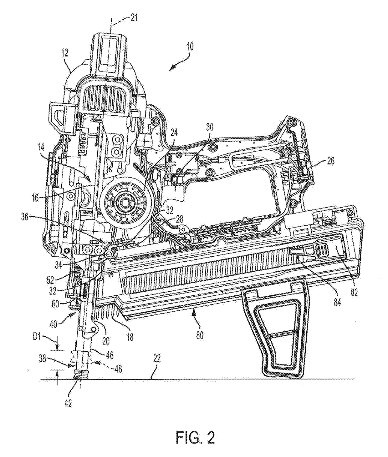
[0030]Referring now to the Drawings and particularly to FIGS. 1-4, a fastening tool 10 in accordance with an embodiment of the present invention includes a housing 12 and a fastener drive system 14 disposed in the housing (FIGS. 2-4). The fastener drive system 14 includes a driver 16 for driving fasteners 18 along a drive track 20 and a drive axis 21, and into a work surface 22. The fastener drive system 14 also includes a motor 24 powered by a battery 26 and operatively associated with the driver 16 to drive the fasteners 18. A contact trip switch 28 and a trigger switch 30 are electrically connected to the fastener drive system 14. Both the contact trip switch 28 and the trigger switch 30 must be closed before the fastening tool 10 fires. The contact trip switch 28, which is normally open, is closed in response to movement of a switch lever 32, which is pivotably mounted in the fastening tool housing 12 about a pivot 34. The contact trip switch 28 and switch lever 32 constitute an...


PUM


Abstract

A fastening tool includes a contact trip operatively associated with a contact trip switch to enable a fastener drive system to be fired when the contact trip reaches a firing position, after having engaged a work surface. If a dry-fire condition exists in a magazine connected to the fastening tool, the movement of the contact trip is completely taken up or absorbed by a biasing agent so that the contact trip switch is not closed. The biasing agent also limits the amount of force that can be applied to the contact trip switch in the event an operator slams the contact trip against a work surface or drops the fastening tool nose-first onto an unyielding surface.

Description

CROSS-REFERENCE TO RELATED APPLICATIONS[0001]The present application claims priority under 35 U.S.C. §119 to U.S. Provisional Application Ser. No. 62 / 356,973 filed on Jun. 30, 2016, which is herein incorporated by reference in its entirety.BACKGROUND OF THE INVENTION1. Field of the Invention[0002]The present invention relates to fastening tools, and more particularly to fastening tools with fastener magazines, and having contact trips engageable with a work surface to enable the fastening tools to fire a fastener.2. Description of the Related Art[0003]Fastening tools, such as concrete nailers, staplers, and other nailers, are normally provided with fastener magazines. Typically, fasteners loaded in the magazine are biased toward a drive track of the fastening tool, so that the fastening tool drive system can drive a fastener into a work surface. However, if the supply of fasteners in the magazine becomes exhausted or “dry” when the fastening tool is fired, the driver of the drive sy...

Claims


Application Information

Patent Timeline
IPC IPC(8): B25C1/00B25C1/06
CPCB25C1/06B25C1/008
Inventor JASKOT, ERIN ELIZABETHBARON, MICHAEL P.GARBER, STUART E.
Owner BLACK & DECKER INC
Learn More