Robot controller

a robot controller and controller technology, applied in the field of robot controllers, can solve the problems of operator injury, liable to be injured, and liable to damage the movable part of the robot or obstacle,

Inactive Publication Date: 2016-03-31
FANUC LTD
View PDF9 Cites 4 Cited by
  • Summary
  • Abstract
  • Description
  • Claims
  • Application Information

AI Technical Summary

Benefits of technology

[0007]According to a first aspect of the present invention, there is provided a robot controller comprising a movement control part which controls an operation of the robot so that a movable part of the robot moves on a predetermined track, and a return control device which controls an operation of the robot so that if a movable part departs from the track during its movement on the track, the movable part will be returned to the track, wherein the return control part limits a force generated by at least one of a plurality of drive devices which drive the robot to a predetermined upper limit value or less.

Problems solved by technology

However, even if the movable part of the robot moves at a low speed to a restart position, serious injury cannot be avoided in the event of a collision.
For example, if the drive torque of the servo motor is relatively large, the movable part of the robot will inflict a large impact force against the object it collides with (for example, an operator or obstacle etc.), and therefore the operator is liable to be injured, or the movable part of the robot or obstacle is liable to be damaged.

Method used


Image

  • Robot controller
  • Robot controller
  • Robot controller

Examples


Embodiment Construction

[0025]Below, an embodiment of the present invention will be explained in detail with reference to the drawings. In the drawings, similar component elements are assigned similar reference notations. Note that the following explanation does not limit the technical scope of the inventions which are described in the claims or the meaning of terms etc.

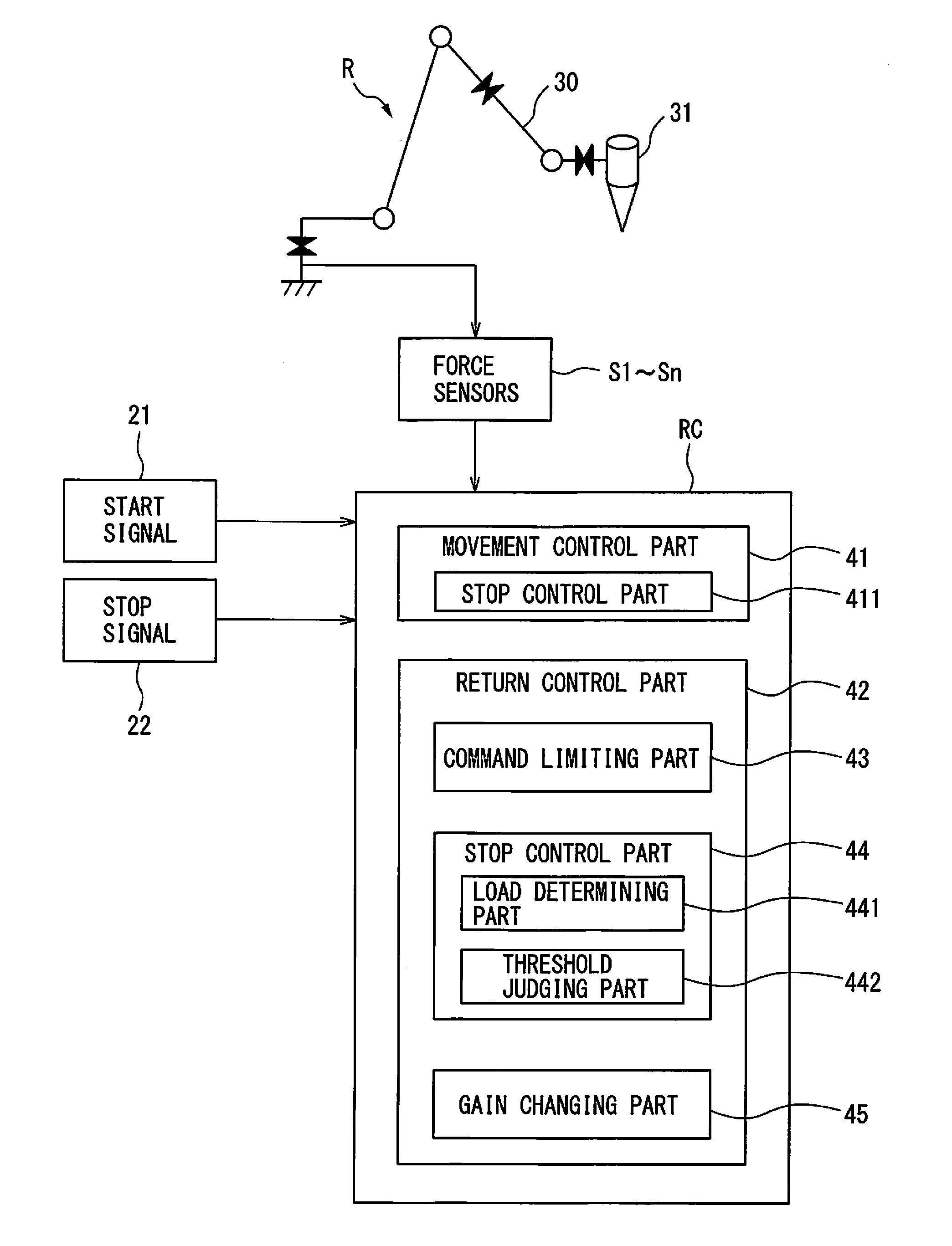
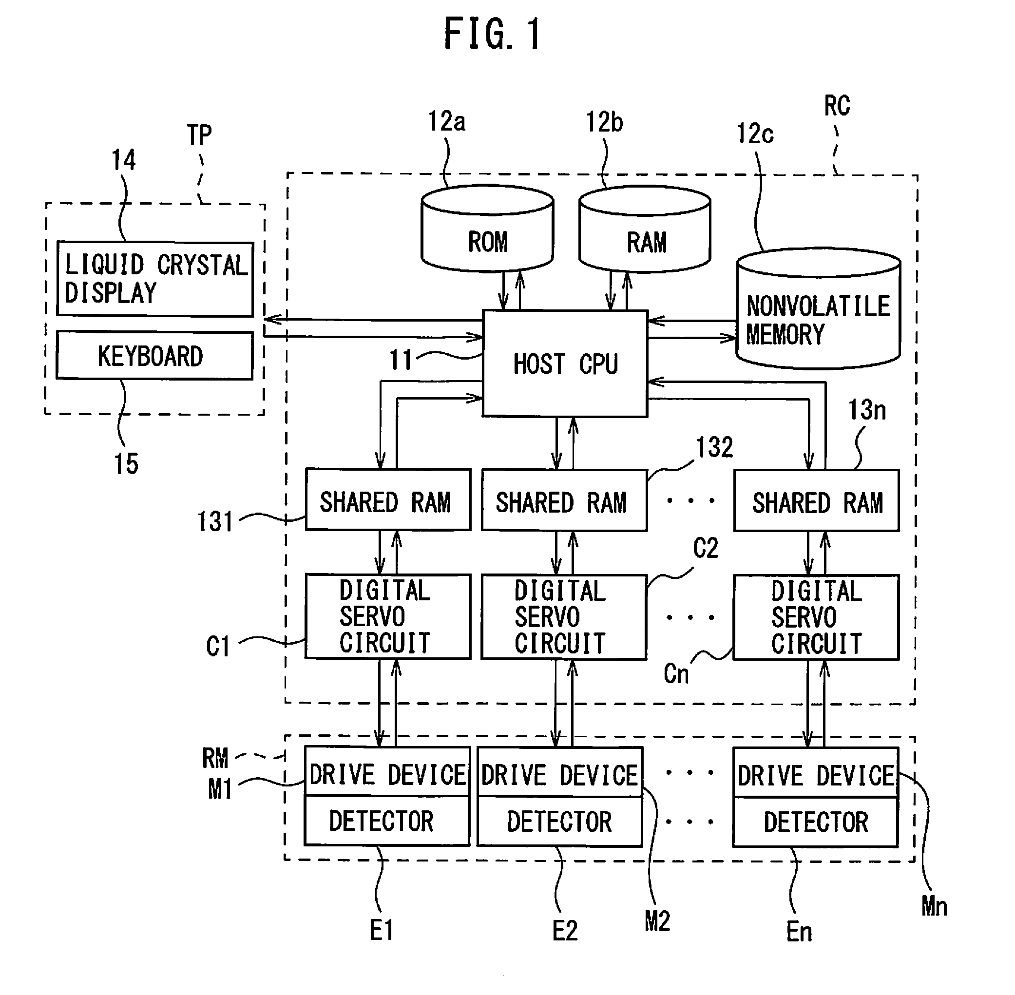
[0026]Referring to FIG. 1 to FIG. 11, a robot controller of one embodiment of the present invention will be explained. FIG. 1 is a block diagram which shows the configuration of a robot system which includes an illustrative robot controller RC of the present embodiment. As shown in FIG. 1, the robot controller RC of the present example is respectively connected to a teaching panel TP and robot mechanism RM. First, the robot mechanism RM in FIG. 1 will be explained. As shown in FIG. 1, the robot mechanism RM of the present example includes a plurality of drive devices M1-Mn which generate drive forces of the robot, and a plurality of detecto...


PUM


Abstract

A robot controller of the present invention comprises a movement control part which controls an operation of a robot so that a movable part of the robot moves on a predetermined track, and a return control device which controls an operation of the robot so that if the movable part departs from the track during its movement on said track, the movable part will return to the track. The return control part is configured to limit a force generated by at least one of a plurality of drive devices which drive the robot, to a predetermined upper limit value or less.

Description

BACKGROUND OF THE INVENTION[0001]1. Field of the Invention[0002]The present invention relates to a robot controller which controls an industrial robot, more particularly relates to a robot controller which comprises a control unit for controlling an operation of a robot so that a movable part which has deviated from a predetermined track will return to the predetermined track.[0003]2. Description of the Related Art[0004]A control device of a vertical articulated robot, horizontal articulated robot, or other industrial robot controls the operation of the robot so that a movable part of the robot (for example, an end effector attached to a front end of an arm) moves on a predetermined track. Further, among control devices of industrial robots, there is one which controls the operation of a robot so that if a movable part of the robot makes an emergency stop as a result of contacting some sort of obstacle, the movable part is returned to a restart position on the original track. Such a...

Claims


Application Information

Patent Timeline
Patent Type & Authority Applications(United States)
IPC IPC(8): B25J9/16
CPCB25J9/1633Y10S901/46Y10S901/01B25J9/1666B25J9/1664B25J9/1674G05B2219/39219G05B2219/43058
Inventor KUROSHITA, TERUKI
Owner FANUC LTD
Why Eureka
Try Eureka