Die bonding method with corner or side contact without impact force

Pending Publication Date: 2022-06-30
SAULTECH TECH
View PDF0 Cites 0 Cited by
  • Summary
  • Abstract
  • Description
  • Claims
  • Application Information

AI Technical Summary

Benefits of technology

This patent aims to provide a method for bonding dies to substrates without using impact force. The method uses non-impact positive pressure to control the contact between the die and the substrate. This results in a small force applied to the die, no damage to the die, and no need for elastic members. The manufacturing cost is also reduced.

Problems solved by technology

The problem with wafer-to-wafer direct bonding is the difficulty to apply to a system on a die.
The cost to make different logic circuits with the same mask from the beginning is high.
However, compared to the wafer-to-wafer direct bonding technology, because the size of the die is smaller, the control of the bonding wave is quite difficult, so the hybrid bond suitable for die-to-wafer has not yet been successfully developed.
The problem with this technology is that it is easy to cause the die and the substrate to jointly envelop the bubbles and generate voids, which causes the die and the substrate to not fully adhere to each other, and the subsequent processing procedures of the die are easily affected by the bubbles, thus reducing the yield rate of products made by subsequent processing.
The problem with this technology is: first, the die has a certain mass, and under the influence of gravity, the die falling to the die placement area with acceleration will produce a greater impact force, which makes the die contact the substrate with more force to cause damage; secondly, it is difficult for the die to be accurately placed on the die placement area.
The problem with this technology is: first, when the die bonding device moves toward the substrate, the elastic members will provide a larger mass inertia of the die, which will cause the die to contact the substrate with a greater impact force and cause damage; second, because of the small size of the die bonding device, the elastic member is very small, difficult to assemble, and the manufacturing cost is relatively high.
In addition, in the above three die bonding methods, when the die is bonded to the substrate, the bonding speed of the die is too fast, causing the die to be easily damaged, skewed or bent.

Method used


Image

  • Die bonding method with corner or side contact without impact force
  • Die bonding method with corner or side contact without impact force
  • Die bonding method with corner or side contact without impact force

Examples


Embodiment Construction

[0038]The accompanying drawings are included to provide a further understanding of the invention, and are incorporated in and constitute a part of this specification. The drawings illustrate embodiments of the invention and, together with the description, serve to explain the principles of the invention.

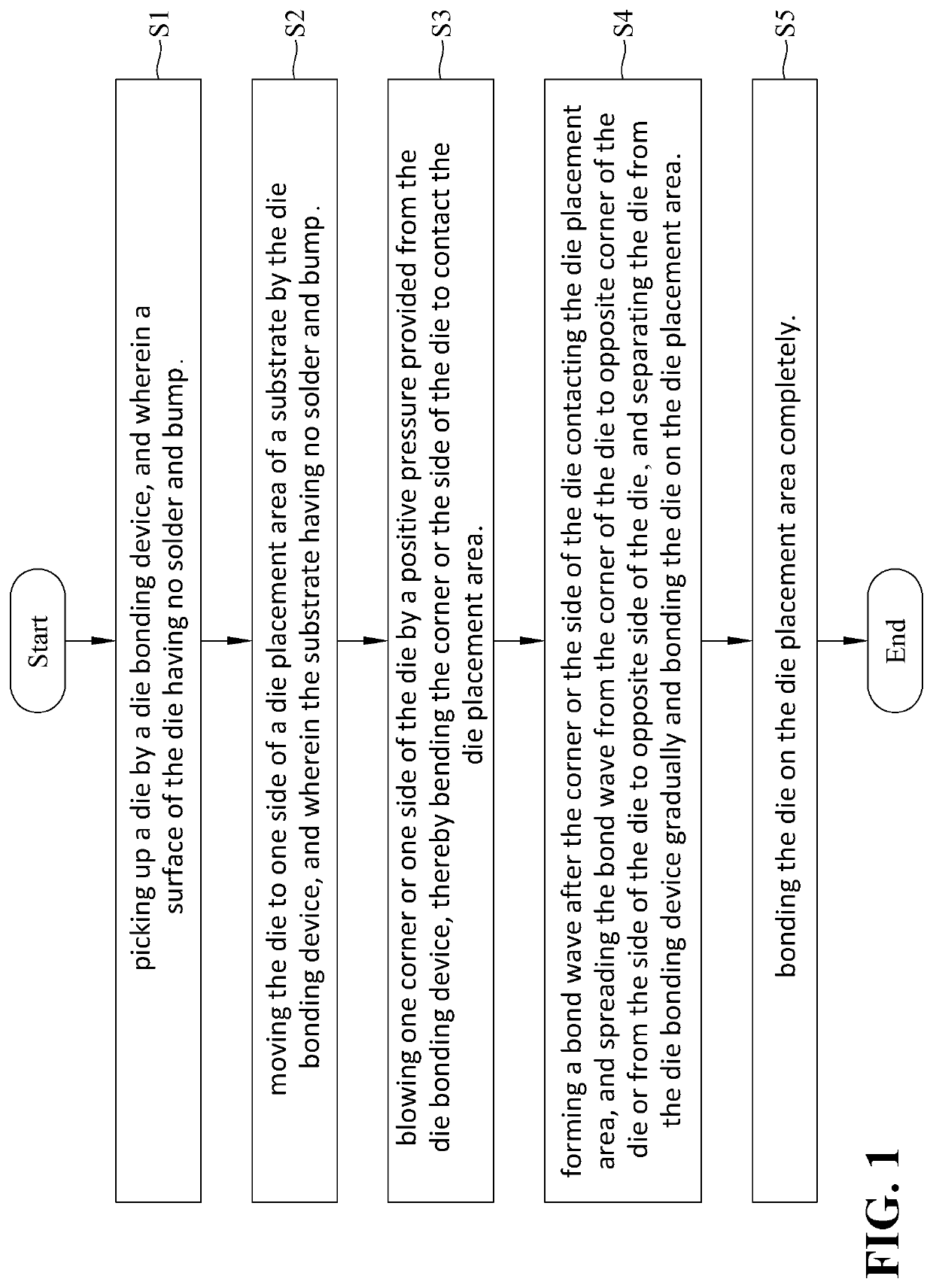
[0039]Refer to FIGS. 1 to 10. The present invention provides a die bonding method with corner or side contact without impact force, including the following steps:

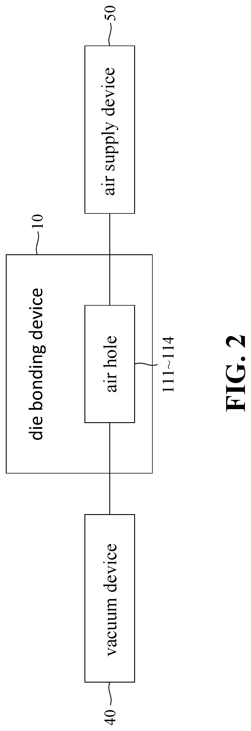
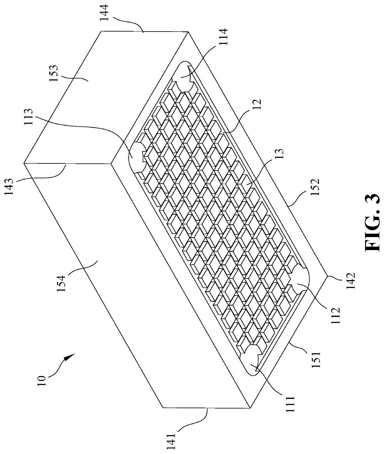
[0040]Step S1, as shown in FIGS. 1 to 4, a die bonding device 10 picks up a die 20, and the die 20 has a surface that is free of solder and bump. More specifically, there is a plurality of die 20 on a first surface 31 of a carrier device 30, and a corner 141 or side 151 of the die bonding device 10 and the rest adsorbs a corner 211 or a side 221 of the die 20 and the rest by a negative pressure 41 to bond the die 20 and pick up the die 20 from the carrier device 30. The carrier device 30 may be a carrier film, a carrier tray...


PUM


Abstract

A die bonding method with corner or side contact without impact force includes the steps: picking up a die by a die bonding device, wherein a surface of the die has no solder and bump; moving the die to one side of a die placement area of a substrate, wherein the substrate has no solder and bump; blowing one corner or one side of the die a positive pressure from the die bonding device to bend the corner / side to contact the die placement area; forming a bonding wave after the corner / side of the die contacting the die placement area, and spreading the bonding wave from the corner / side to opposite corner / side of the die, and separating the die from the die bonding device gradually and bonding the die on the die placement area; and bonding the die on the die placement area completely.

Description

BACKGROUND OF THE INVENTION1. Field of the Invention[0001]The present invention relates generally to a die-bonding method, and more particularly, to a die bonding method with the corner or side contact of the substrate without impact force.2. The Prior Arts[0002]The integrated circuit is fabricated on a semiconductor wafer is mass and through multiple processes, and then the wafer is further divided into a plurality of dies. In other words, the die is a small piece of unpackaged integrated circuit made of semiconductor materials. The divided dies are neatly attached to a carrier device, and then a carrier frame is responsible for transporting the carrier device, and then the dies are sequentially transferred to a plurality of dies placement area of a substrate to facilitate subsequent processing procedures.[0003]Wafer-to-wafer direct bonding technology has been practiced for many years and belongs to the front-end process, which can facilitate the control of cleanliness and precisio...

Claims


Application Information

Patent Timeline
IPC IPC(8): H01L23/00
CPCH01L24/80H01L24/74H01L2224/8009H01L2224/80895H01L24/81H01L2224/81053H01L24/75H01L2224/75745H01L2924/00015H01L2224/80201H01L2224/80896H01L2224/80905H01L2224/81H01L2924/00012H01L2924/00014H01L21/52H01L21/67721H01L21/6838H01L21/67144
Inventor LU, YEN HAO
Owner SAULTECH TECH
Why Eureka
Try Eureka