

Composite Bridge Deck and Bridge Construction
- Summary
- Abstract
- Description
- Claims
- Application Information
AI Technical Summary
Benefits of technology
Problems solved by technology
Method used
Image

Examples
Embodiment Construction
[0024]The following is a description of exemplary embodiments of the invention, given by way of example only and with reference to the figures.
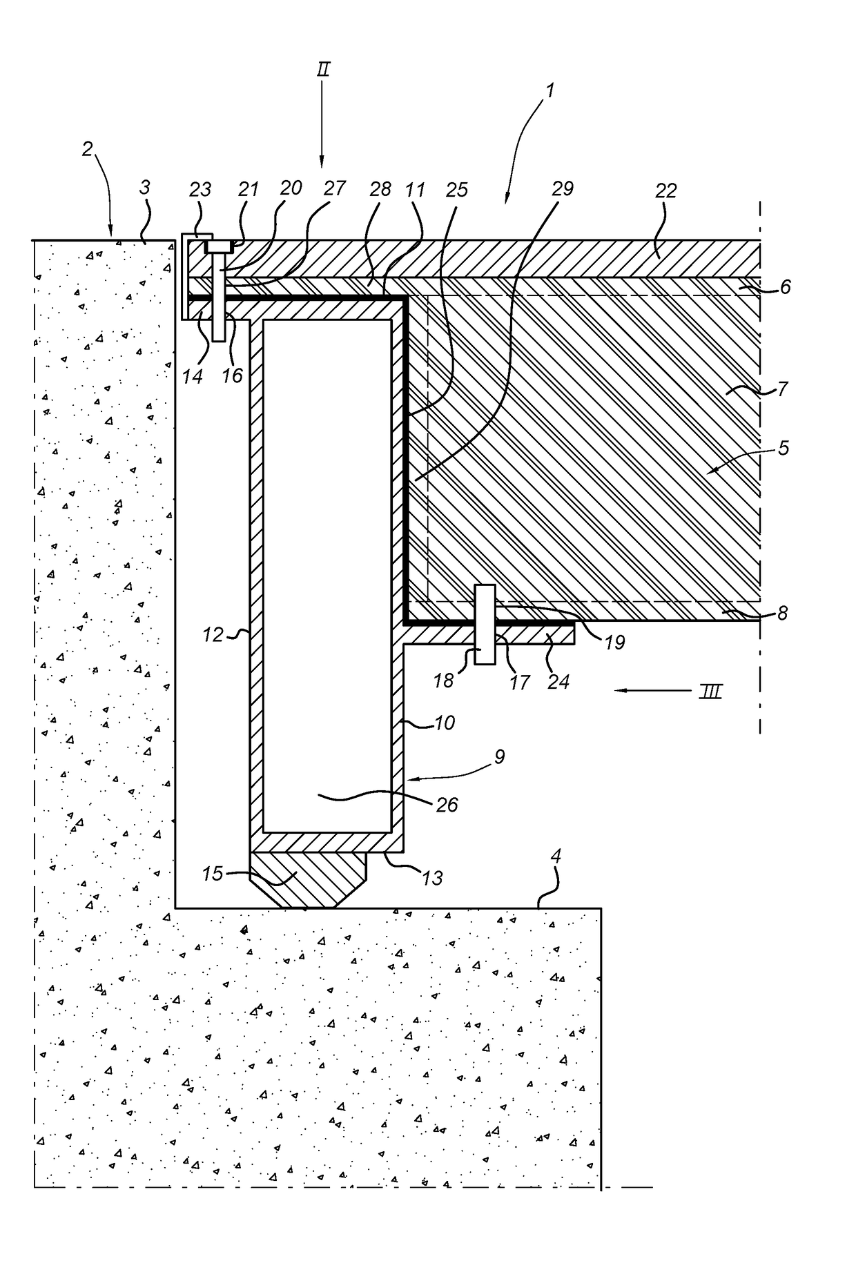
[0025]FIG. 1 shows in vertical cross section, a bridge deck 1 with an abutment 2 which in the example shown has a road surface 3 and a support 4 for the bridge deck 1 at a lower level. The bridge deck 1 itself is formed by a composite panel 5, known in itself, together with the steel edge beam 9. This composite panel diagrammatically comprises the top plastic skin 6, a bottom plastic skin 8 and the core 7 in-between. Around this, a bulkhead 29 is provided. This bulkhead 29 and the bottom plastic skin 8 of the composite panel 5 abut the front side 10 of the edge beam 9. The top plastic skin 6 extends with the protruding part 28 past the core 7 to over the top side 11 of the edge beam 9.
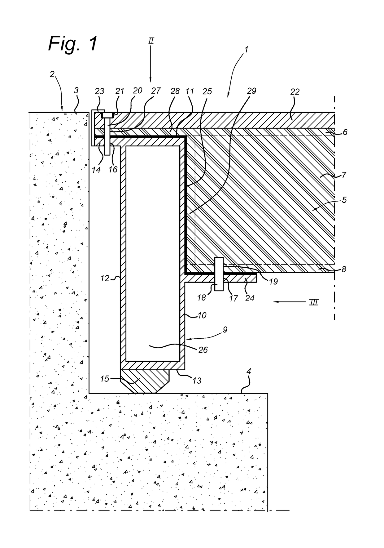
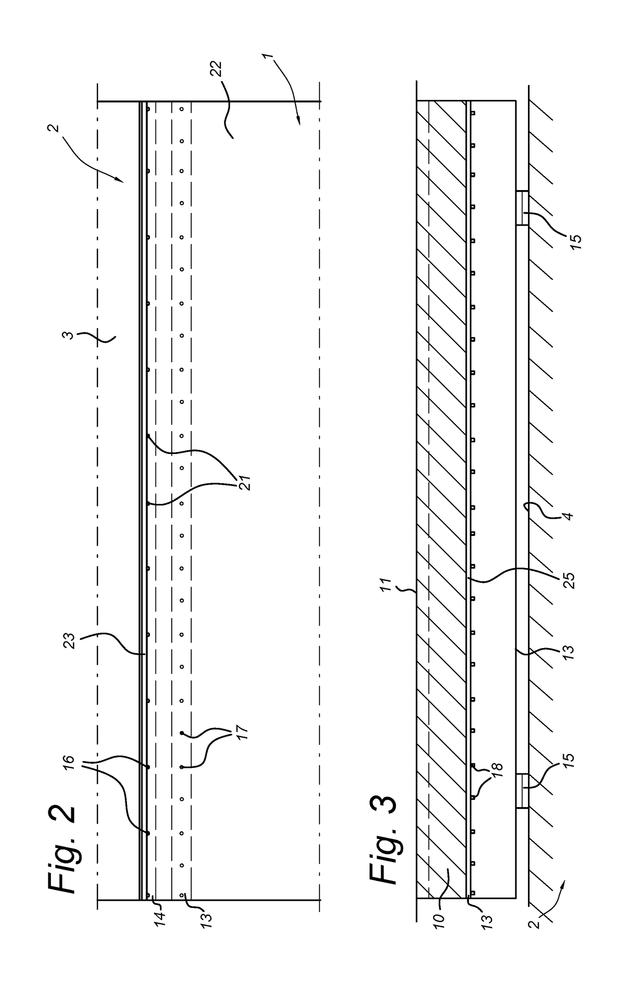
[0026]The edge beam 9 has a bottom flange 24 on its front side 10. On the opposing back side 12 of the edge beam 9 is a top flange 14 which connects to the top ...
PUM
| Property | Measurement | Unit |
|---|---|---|
| Width | aaaaa | aaaaa |
| Dimension | aaaaa | aaaaa |
| Height | aaaaa | aaaaa |
Abstract
Description
Claims
Application Information