Composite bridge deck and bridge construction

a composite bridge and bridge technology, applied in the field of composite bridges, can solve the problems of uneven deformation, failure of adhesion, and site of transition from steel edge, and achieve the effect of positive mechanical connection

Active Publication Date: 2019-02-19
FIBERCORE IP
View PDF19 Cites 0 Cited by
  • Summary
  • Abstract
  • Description
  • Claims
  • Application Information

AI Technical Summary

Benefits of technology

[0007]In the bridge deck according to this aspect, the top layer of the composite panel is configured such that this layer extends relative to the core of the composite panel. The top layer, in contrast to the core, does not butt up against the steel edge beam but extends over this. The steel edge beam thus forms a component of the bridge deck which is fully concealed below the top layer of the composite panel. The top layer of the composite panel, in other words the protruding part of the top plastic skin, completely covers the edge beam. As a result, wheel contact only occurs on the surface of the top layer, resulting in a more uniform load development from the bridge deck to the adjacent abutment and vice versa.
[0008]In contrast to the known bridge decks, there are no significant differences in deformation, which helps to safeguard the integrity of the bridge deck. As a result, there is no or virtually no cause for crack formation, and seepage of moisture and local freezing are avoided.
[0012]In this way, a positive mechanical connection is ensured between the edge beam and the composite panel. In a preferred embodiment, the openings may form a row of pairs of openings. This row extends in the longitudinal direction of the edge beam. Of this row, at least one pair of openings and the associated peg cooperate closely so as to ensure a fixed position of the edge beam and the composite panel relative to each other. The other pairs of openings however have the form of a slot, the largest dimension of which is directed in the longitudinal direction of the edge beam, to compensate for the expansion differences between the edge beam and the composite panel.
[0013]At the free edge of the protruding part of the top plastic skin and the edge beam, an angle profile may be provided, one leg of which covers the top surface of the protruding part or a cover layer located on the protruding part, and the other leg of which extends along the border of the protruding part of the top plastic skin, the edge beam and any cover layer present on the protruding part. Such an angle profile offers further protection of the laminate of cover layer, top plastic skin and flange of the edge beam.

Problems solved by technology

Although a bridge deck produced in this way is ideal for heavy traffic, it is found however in practice that, in the long term, problems can occur at the site of the transition from the steel edge beam to the composite material of the bridge deck.
These problems are partly caused by the fact that the steel edge beam has a greater stiffness than the composite material.
The forces exerted on the bridge construction from the wheel loads of the road traffic therefore lead to uneven deformations occurring at the transition between the steel edge beam and the composite material.
In the end, the adhesion can fail.
The resulting crack formation in the surface of the bridge deck allows moisture to seep in, such that corrosion and further cracking can occur in frost.

Method used


Image

  • Composite bridge deck and bridge construction
  • Composite bridge deck and bridge construction

Examples


Embodiment Construction

[0024]The following is a description of exemplary embodiments of the invention, given by way of example only and with reference to the figures.

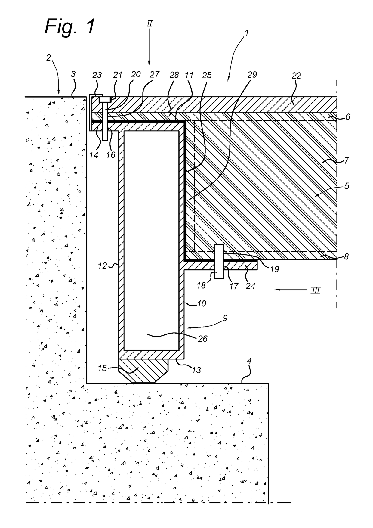
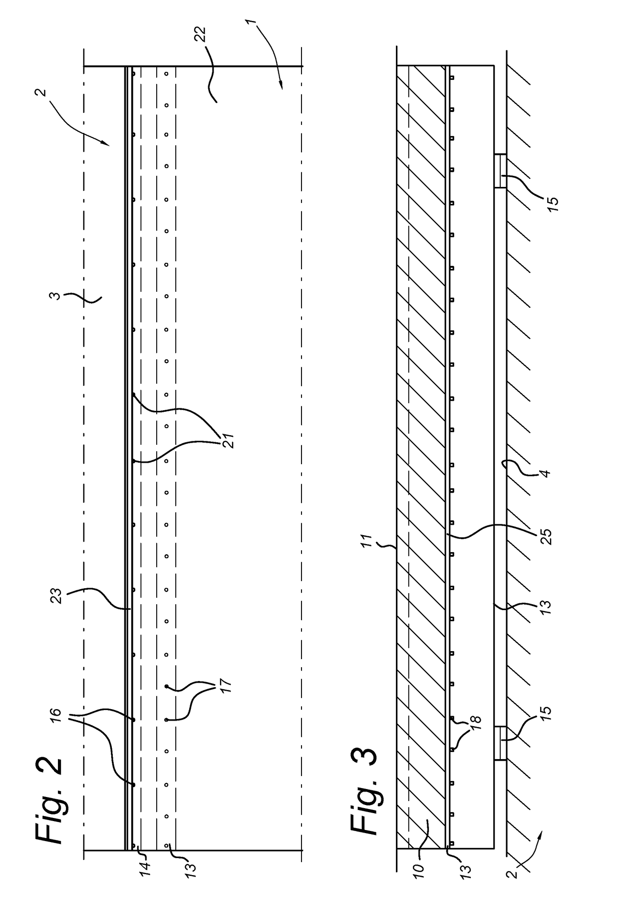
[0025]FIG. 1 shows in vertical cross section, a bridge deck 1 with an abutment 2 which in the example shown has a road surface 3 and a support 4 for the bridge deck 1 at a lower level. The bridge deck 1 itself is formed by a composite panel 5, known in itself, together with the steel edge beam 9. This composite panel diagrammatically comprises the top plastic skin 6, a bottom plastic skin 8 and the core 7 in-between. Around this, a bulkhead 29 is provided. This bulkhead 29 and the bottom plastic skin 8 of the composite panel 5 abut the front side 10 of the edge beam 9. The top plastic skin 6 extends with the protruding part 28 past the core 7 to over the top side 11 of the edge beam 9.

[0026]The edge beam 9 has a bottom flange 24 on its front side 10. On the opposing back side 12 of the edge beam 9 is a top flange 14 which connects to the top ...


PUM

PropertyMeasurementUnit
widthaaaaaaaaaa
dimensionaaaaaaaaaa
distancesaaaaaaaaaa

Abstract

A bridge construction having a bridge support or abutment and a bridge deck supported thereon. The bridge deck includes a composite panel with a top plastic skin, a bottom plastic skin and a core arranged between and attached to the plastic skins. The bridge deck also includes an edge beam extending along at least one edge of the composite panel and resting on the bridge support. The top plastic skin has a protruding part which protrudes laterally relative to the core and the bottom plastic skin. The protruding part of the top plastic skin extends over and is attached to a top side of the edge beam, and both the core and the lower plastic skin extend laterally up to a front side of the edge beam.

Description

TECHNICAL FIELD[0001]The invention relates to a bridge deck comprising a composite panel with a top plastic skin, a bottom plastic skin and a core between and attached to the plastic skins, and an edge beam on at least one edge of the composite panel.BACKGROUND ART[0002]Such a bridge deck is known. The composite panel thereof is often provided with steel edge beams at the edges. These steel edge beams may extend transversely to the longitudinal direction of the bridge deck, and conduct the forces which result from the weight of the bridge deck and the weight of the road traffic travelling over the bridge deck. The concentrated imposition forces which occur at the site of the support of the edge beam on the bridge support can therefore be distributed regularly over the composite panel. Also, such edge beams may be provided at the longitudinal edges of the composite panel.[0003]Although a bridge deck produced in this way is ideal for heavy traffic, it is found however in practice that...

Claims


Application Information

Patent Timeline
Patent Type & Authority Patents(United States)
IPC IPC(8): E01D19/00E01D19/02E04B5/02E01D19/12E04C3/04E01D19/04E01D101/40
CPCE01D19/125E01D19/02E04B5/026E04C2003/0465E01D2101/40E04C2003/0439E01D19/04
Inventor PEETERS, JOHANNES HENDRICUS ALPHONSUS
Owner FIBERCORE IP
Why Eureka
Try Eureka