Push-pull structure

Inactive Publication Date: 2018-01-25
SAMSUNG SDS CO LTD
View PDF6 Cites 0 Cited by
  • Summary
  • Abstract
  • Description
  • Claims
  • Application Information

AI Technical Summary

Benefits of technology

[0004]Embodiments of the present disclosure provide a push-pull structure cap

Problems solved by technology

However, in the above-described push-pull type door lock, since there is a difficulty of separating most of the door lock for push-pull

Method used


Image

  • Push-pull structure
  • Push-pull structure
  • Push-pull structure

Examples


Example

[0031]Hereinafter, detailed embodiments of the present disclosure will be described with reference to the drawings. However, they are merely examples and the present disclosure is not limited thereto.

[0032]In the description of the embodiments of the present disclosure, a certain detailed explanation of a well-known function or component of the related art will be omitted when it is deemed that it may unnecessarily obscure the essence of the present disclosure. Also, the below-described terms are defined in consideration of functions thereof in the embodiments, which may vary according to intentions of a user and an operator or practice. Accordingly, the definitions thereof will be given based on the content throughout the specification.

[0033]The technical concept of the present disclosure is defined by the claims, and following embodiments are merely a way for efficiently explaining the technical concept of the present disclosure to one of ordinary skill in the art.
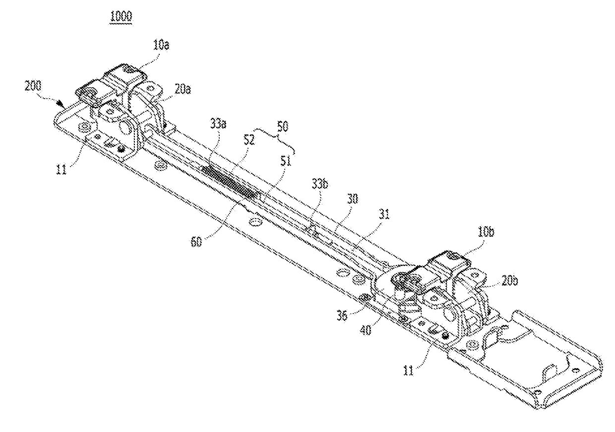
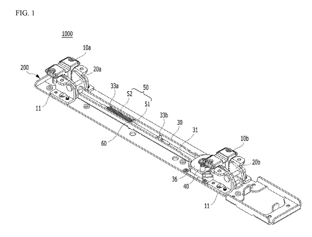
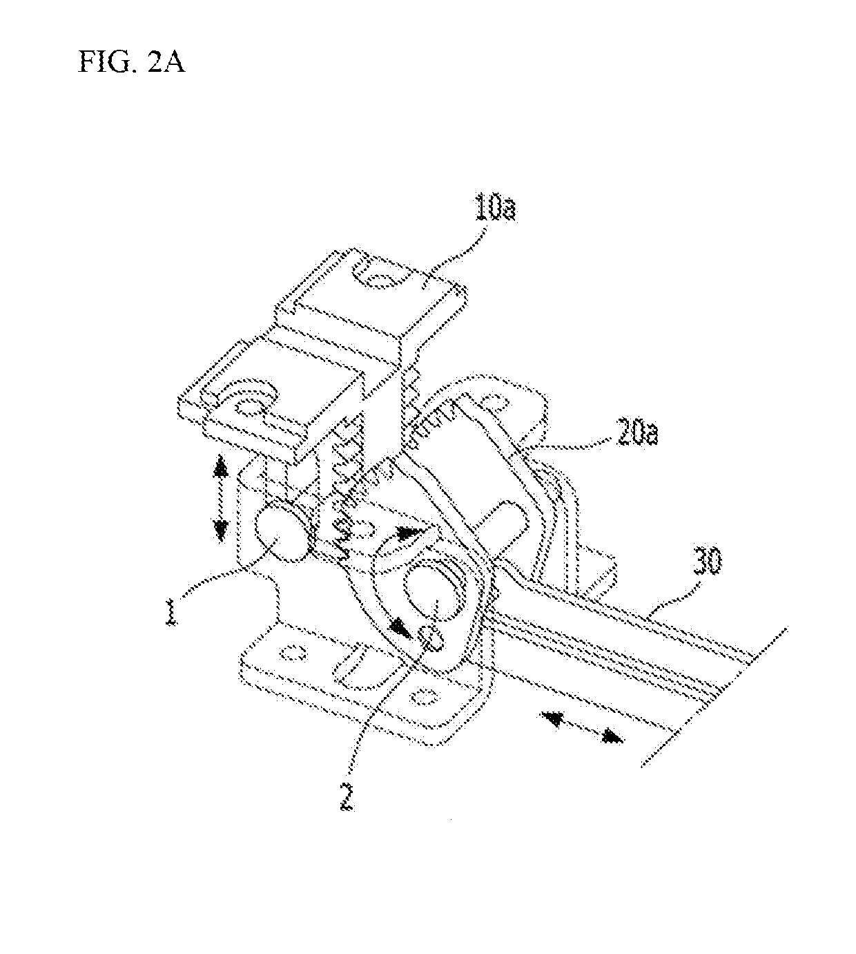
[0034]A push-pul...


PUM


Abstract

One embodiment of the present disclosure relates to a push-pull structure. According to one embodiment of the present disclosure, there is provided a push-pull structure including a first mobile portion and a second mobile portion installed at a handle portion, a first pivoting portion that pivots due to a movement of the first mobile portion and a second pivoting portion that pivots due to the second mobile portion, a connector that connects the first pivoting portion with the second pivoting portion, a pivoting body linked with the connector and connected to a mortise to fasten or release a latch, a reaction structure disposed in the connector and including an elastic member, and a switching member separated from or mounted on the reaction structure. Here, a position of the elastic member is changed by the switching member.

Description

CROSS-REFERENCE TO RELATED APPLICATION[0001]This application claims priority to and the benefit of Korean Patent Application No. 10-2016-0084297, filed on Jul. 4, 2016, the disclosure of which is incorporated herein by reference in its entirety.BACKGROUND1. Field[0002]One embodiment of the present disclosure relates to a push-pull structure.2. Discussion of Related Art[0003]As one of the various types of door locks, there is a push-pull type door lock in which a dead bolt or a latch bolt is released when a force is applied in a direction to open. In the push-pull type door lock, the dead bolt or the latch bolt is released by applying a force to an internal handle and an external handle in a direction to open the door. However, in the above-described push-pull type door lock, since there is a difficulty of separating most of the door lock for push-pull switching and the door lock does not operate when the handle is partially pushed, it is impossible to provide operational reliability...

Claims


Application Information

Patent Timeline
IPC IPC(8): E05B65/10
CPCE05B65/1053E05B63/0056E05B63/22E05B1/0038E05B1/0053E05B9/02E05B15/101
Inventor YOO, SEONG-JONGKIM, YOUNG-KWON
Owner SAMSUNG SDS CO LTD
Why Eureka
Try Eureka