This helps you quickly interpret patents by identifying the three key elements:
Problems solved by technology
Method used
Benefits of technology
Benefits of technology
This patent describes a system that allows a surgeon to view the operating field using a tablet computer. The tablet can be held in front of the surgeon by a nurse or placed on a stand for easy viewing. The system also allows for easy magnification of the image on the tablet using a pinch maneuver. It is suggested that the tablet and stand be covered with a clear and sterile plastic membrane to prevent contamination. Additionally, the patent discusses the use of a disposable lighting and image gathering device that can be attached to existing surgical retractors. The disposable component can be given to patients and used for review clinics. The technical effects of this system include improved visibility and access during surgical procedures and the ability for patients to have an ongoing relationship with their surgeon through regular review and examination.
Problems solved by technology
The field of surgery is a difficult art to practice.
A generally held misconception is that surgery requires particularly high levels of manual dexterity.
Despite the relatively simple nature of surgical tasks however, surgery is difficult.
In particular, many people are shocked to learn that surgeons often cannot clearly see those tissues and vital structures being operated on in the depths of a wound.
The great unrecognised problem in surgery is the fact that surgeons cannot see what they are doing, especially when they need to do so most.
In fact, the need for such powerful light sources should be an indication that seeing structures deep in a wound is a major unresolved problem.
Surgery becomes difficult when clear visualisation of structures cannot be achieved.
Further, a primary reason for surgical error lies in poor visualisation of anatomical structures.
Poor visualisation increases operating time and increases the risks.
Fiberoptic endoscope devices are usually separately lit up by means of an external lighting unit which is heavy and expensive and non disposable.
The non disposable fiberoptic cables are additionally expensive to clean and maintain.
Moreover, the cables themselves are easily broken by twisting thus degrading image quality over time with repeated use.
However when looking through the eyepiece the surgeon's view is restricted only to that view obtained from the eyepiece.
Thus it is not easy for surgeons to switch between direct visualisation of a wound and the fiberoptic cable endoscope view during procedures.
The size of the lens and eyepiece and its position makes it impossible to see around it.
Further, it is time consuming to position the lens correctly.
Thus alternating between a direct view of the wound to a magnified views is not easy.
Further, operating using microscopes makes it inconvenient to change instruments or pass instruments from scrub nurse to surgeon.
Further still, it is difficult to pass instruments between scrub nurse and surgeon when using such microscopes without the risk that the heavy lens unit might be knocked and thereby moved out of focus; thus wasting surgical time continually adjusting and repositioning the said microscope.
Operating microscopes are additionally expensive and heavy pieces of equipment difficult to clean and maintain.
Method used
Image
Click on the blue label to locate the original text in one second.
Reading with bidirectional positioning of images and text.
Examples
embodiment 1
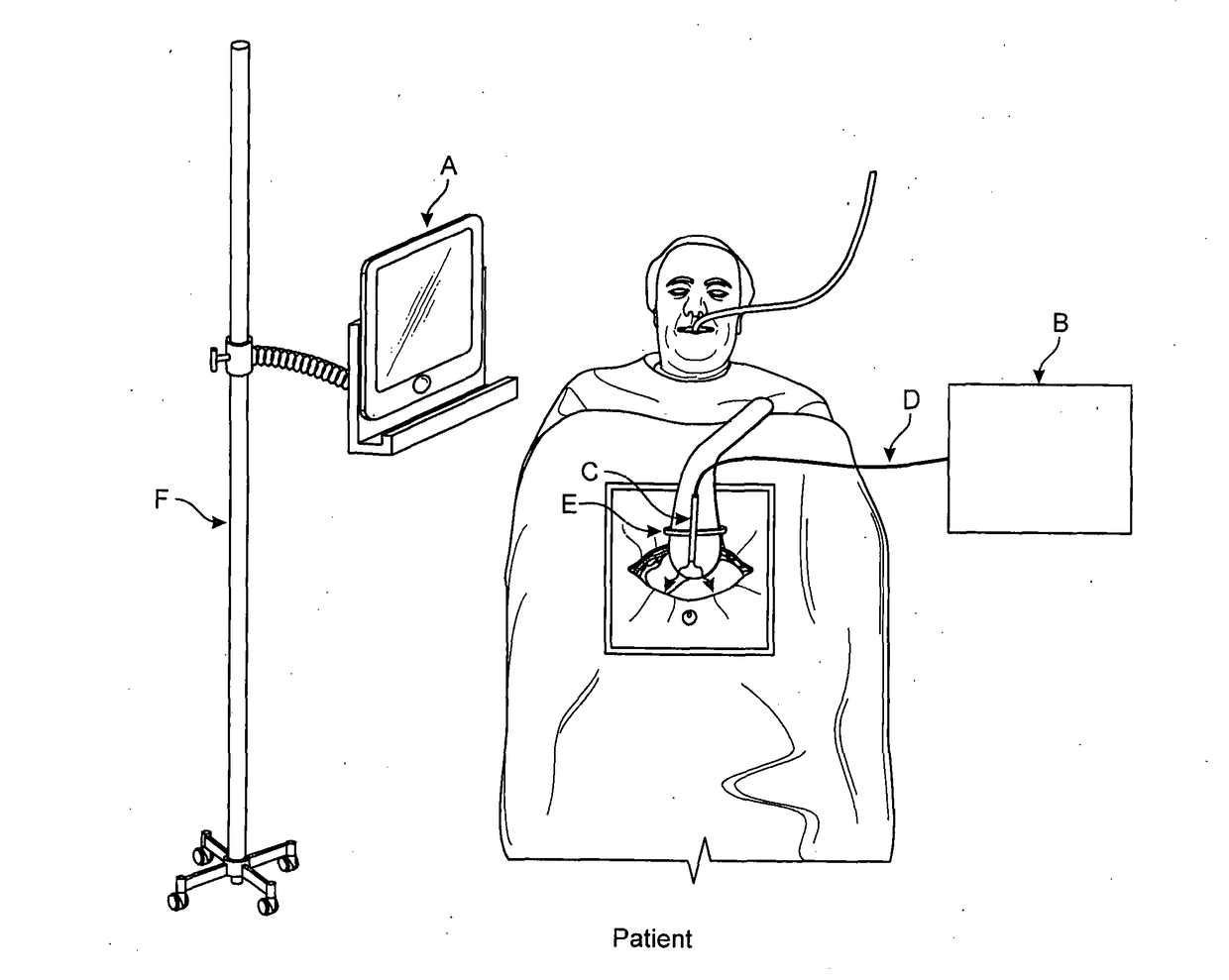
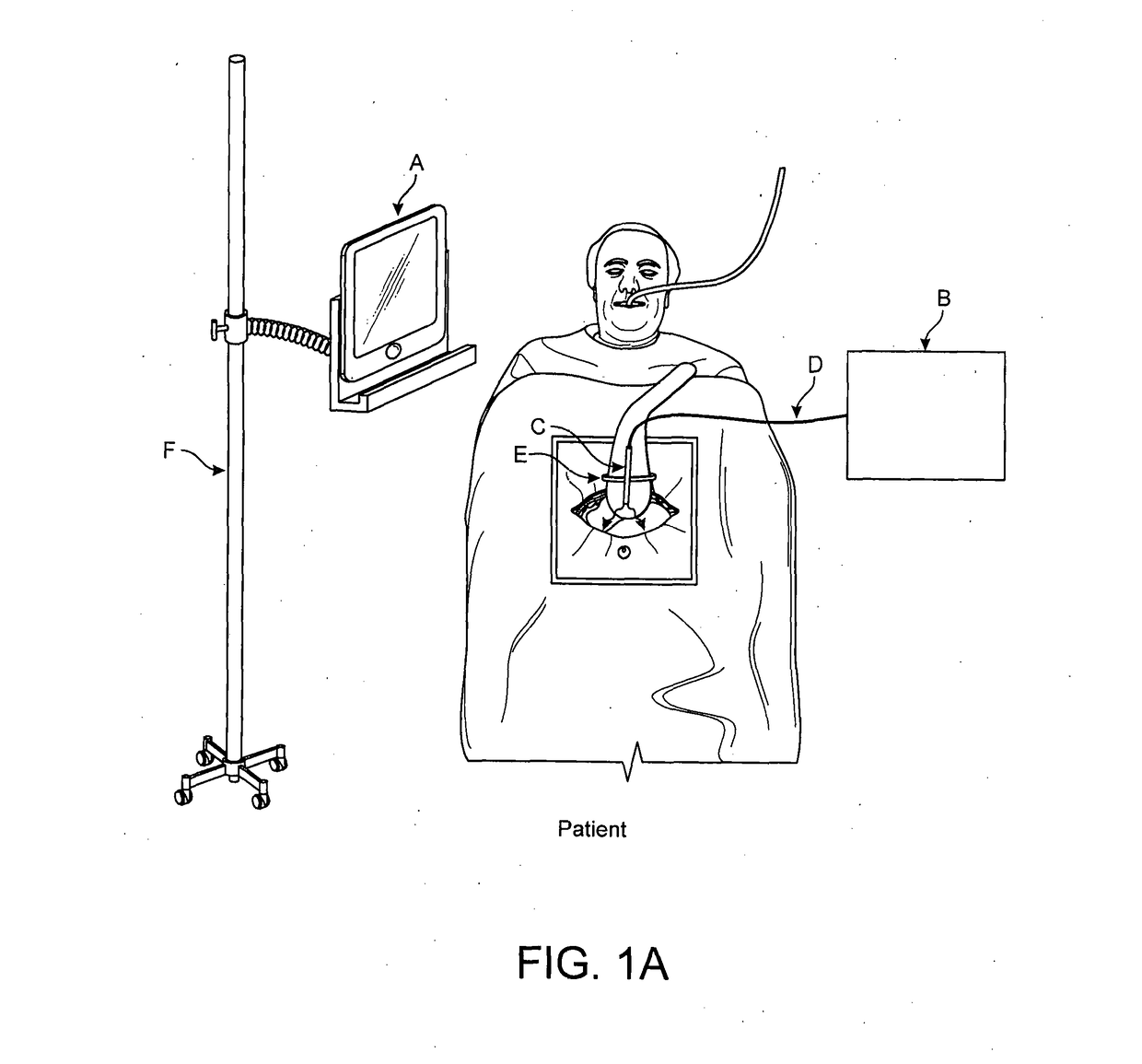
[0070]Attention is drawn to FIG. 1A which depicts the invention in use in general terms with reference to one particular mode of use and one particular embodiment.
[0071]Figure 1A depicts a Tablet PC, normally hand-held, but in this instance supported on a stand, suitable for use in an operating theatre, which stand holds the Tablet PC in a suitable manner to permit the surgeon to view images displayed on it.
[0072]The hand-held PC tablet PC or equivalent, Component A of the system, displays images from the wound to the surgeon.
[0074]The apparatus comprising a plurality of objects adapted for use in clinically invasive procedures is depicted comprising various components in particular;
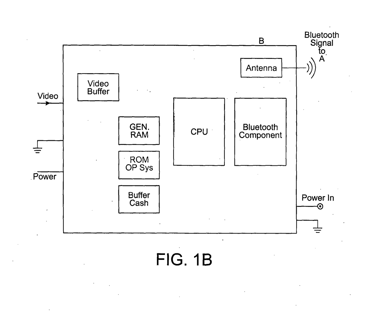
[0075]a second small computer or dongle, Component B of the system having its own operating system, which Component B transmits video image data via BLUETOOTH® signals or equivalent to the Tablet PC, ...
embodiment 2
[0131]Attention is directed to FIG. 2 which depicts a cheaper embodiment variation of the disposable image gathering and light delivery component, Component C. This variation provides a means of preserving the CMOSimage sensorchip circuit sub-component and LED sub-components to avoid disposing of these by incineration. FIG. 2 depicts a female hood attachment which is capable of attaching a USB cable or equivalent by means of a USB connection or similar connection which would attach to the micro computerdongle Component B to the said hood.
[0132]This USB connection and cabling would provide power ground and data bus services to the CMOSimage sensor component and LED sub-component located in the hood. The female end of the hood would typically have an appropriately shaped opening which may be cylindrical or rectangular, but not necessarily limited to a cylindrical or a rectangular shaped opening however the said opening would correspond with the shape of the top of Component C such...
embodiment 3
[0138]Attention is drawn to FIG. 3 which depicts an illustration of a more expensive embodiment of Component C of the apparatus forming the system for use in clinically invasive procedures and surgery.
[0139]In this embodiment, Component C, comprises its usual sub-components as set forth herein above in Embodiment 1 combined additionally with components normally present in Component B, the micro computerdongle component with its own independent operating system.
[0140]In particular this expensive embodiment of Component C comprises:
[0141]a Perspex window(s) at the wound end, which may serve the functionality of window and lens; together with
[0142]the CMOS image capturechip behind one Perspex window, linked by
[0143]a data bus; which databus runs upwards to the processing chips all contained in the same sterile disposable device; the bus provides power and ground and transmits video data upwards by the same bus, alongside the CMOS image sensor chip circuit, video camera chip, or close...
PUM
Abstract
A apparatus adapted for use in clinically invasive proceedures comprising a plurality of objects forming a system, the object of which being to display to a surgeon or clinician the image of tissues and to improve the visualisation of tissue, and comprising: at least two computers or computer like devices containing microprocessors running independent operating systems; wherein, Component A, is any commercially available Tablet PC or smart phone or computer device capable of displaying high-definition video images having a touch screen capable of the pinch manouver; and is linked by BLUETOOTH® or equivalent to a second computer like device, Component B which has a separate microprocessor and operating system; and is linked using cables to a small sterile disposable component Component C which can attach to existing surgical retractors and comprises a LED (light emitting diode) or equivalent and a CMOS pixel sensor chip or equivalent.
Description
[0001]The present disclosure claims priority from the folowing UK patent applications: GB1511341.8 filed on 29 Jun. 2015; GB1502834,3 filed on 19 Feb. 2015; GB1412359.0 filed on 11 Jul. 2014; and GB1412089.3 filed on 7 Jul. 2014.TECHNICAL FIELD[0002]The invention discloses an apparatus adapted for use in invasive clinical procedures comprising a plurality of devices. In particular, the present apparatus forms a system from a plurality of objects working in concert comprising: computers; novel devices with lighting and camera image sensor components; attachments; connecting and covering devices working together as a system whose object is to improve visualisation during surgery. More particularly the invention also discloses novel devices useful in the performance of surgery and other invasive clinical procedures.BACKGROUND ART[0003]The field of surgery is a difficult art to practice. A generally held misconception is that surgery requires particularly high levels of manual dexterity...
Claims
Application Information
Patent Timeline
Application Date:The date an application was filed.
Publication Date:The date a patent or application was officially published.
First Publication Date:The earliest publication date of a patent with the same application number.
Issue Date:Publication date of the patent grant document.
PCT Entry Date:The Entry date of PCT National Phase.
Estimated Expiry Date:The statutory expiry date of a patent right according to the Patent Law, and it is the longest term of protection that the patent right can achieve without the termination of the patent right due to other reasons(Term extension factor has been taken into account ).
Invalid Date:Actual expiry date is based on effective date or publication date of legal transaction data of invalid patent.

